
4 essential elements for high quality FSW welding
Unlocking the secrets to perfect FSW welds: a guide to key elements and techniques.

For the proper execution of your friction stir welding operation, it is essential to consider the following 4 elements:
In this article we will go through all of them to understand the subtleties to get a perfect FSW weld.

The importance of clamping jig
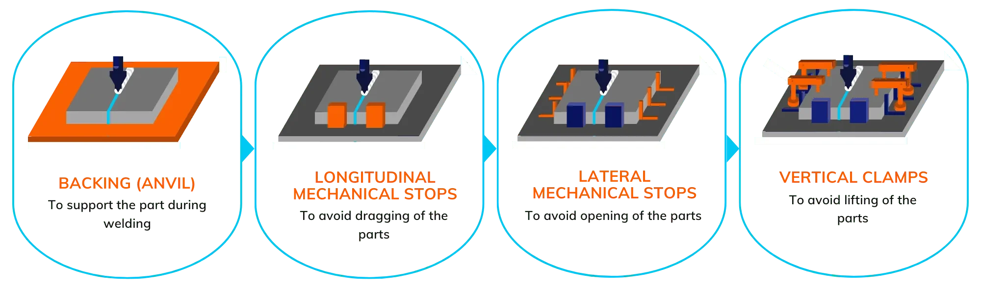
The clamping jig fulfils several functions by means of a backing, a Z-clamp and an XY-clamp:
There are two types of clamping jig: manual and automatic. Manual clamping jig is preferred for welding small series of parts or prototypes because it is less expensive. Automatic clamping jig should be used for welding large series of parts because it is more profitable than manual clamping jig. There are two types of automatic clamping jig: pneumatic, which uses pressurised air, and hydraulic, which uses pressurised oil.
For more information on clamping jig, see our article “The importance of clamping jig“.
Tool geometry
The FSW tool consists of two main parts: the shoulder and the pin.
The shoulder
It will heat the material by friction and guarantee its good mixing to obtain a defect-free weld. The diameter of the shoulder is calculated according to the thickness of the part to be welded.
The shoulder is positioned on the surface of the parts and rubs against the material to create the frictional heat necessary to soften the parts (approximately 400°C for aluminium).
Because of its shape and size, the shoulder will confine the parts to be welded and prevent them from leaving the welding area.

The pin
The pin is threaded to increase the mixing of the material as it rotates. Due to its shape, it will plastically deform the material by penetrating the parts to be welded: an additional amount of heat is then provided by this shearing effect. The length of the pin depends on the thickness of the parts to be welded and the welding configuration (butt or lap weld, see our article “Friction stir welding: comparison between butt and lap welding“.
If the length of the pin is insufficient, there is a risk of lack of penetration. On the other hand, if it is too long, there is a risk of damaging the baking.
The choice of tool depends on the material of the parts to be welded and the welding parameters. Do not hesitate to consult one of our experts to help you choose the right tool for your specific application.
Force control
Force control is an essential element to obtain a perfect weld. It is a matter of knowing and controlling the force to be exerted during the FSW welding operation to place the tool on the parts and to have good compactness and avoid porosity.
The force control allows the positioning of the tool to be adjusted to the variations in the surface relief of the parts to be welded. Indeed, to guarantee the quality of the weld, the penetration of the tool in the part must be constant. With force recording, the vertical force exerted during the welding operation will be recorded to ensure good repeatability of the weld and to allow quality control.

Welding parameters
The welding parameters include the speed of rotation, the feed rate and the force exerted vertically during the welding operation.

Rotation in RPM

Welding speed in mm/min

Z force in kN
The force exerted is measured in kilo Newton – kN, and is called the Z-force. If this force is too low, there will be a risk of lack of penetration of the tool and therefore a risk of defects in the compactness of the weld. On the other hand, if it is too high, the tool will be pushed too far into the material and the welded section will be reduced.
The rotation speed is measured in revolutions per minute – RPM. The faster the tool turns, the hotter the material will be. It is therefore important to monitor and control this speed to achieve a perfect FSW weld.
The welding speed is measured in mm/min. The faster the tool feeds, the colder the material will be. Like the speed of rotation, the feed rate must therefore be controlled and managed.
| Materials / thickness | Rotation | Z force |
| 5754 H11 – 2 mm on 6061 T6 (lap) | 1000 RPM | 7000 N |
| 6061 T6 – 12 mm (butt – double pass of 6 mm) | 1200 RPM | 8000 N |
| 5754 H11 – 2 mm (butt) | 3000 RPM | 6000 N |
| 5754 H11 – AS10Fe (casting) 2 mm (butt) | 2400 RPM | 6000 N |
| 7075 T6 – 2 mm on 2024 T3 – 3 mm (lap) | 900 RPM | 6000 N |
| 5754 H11 – 2 mm on S235 – 1 mm (lap) | 1000 RPM | 4000 N |
The stability of the FSW process can be quantified by the feed ratio (k) which is calculated as follows:

With v the welding speed and ω the rotation speed.
The smaller k is, the hotter the material will be and vice versa. The right range of k must therefore be determined in order to find the right welding temperature.
To guarantee the quality of your FSW weld, it is imperative to take into account the adaptation of the clamping tool to your part, the geometry of the tool according to the thickness and the material of your part, as well as the welding parameters: force exerted, rotation speed and welding speed.
Contact FSW experts
The Stirweld team, expert in the field of friction stir welding, will assist you in defining your welding parameters, in the choice of your tool and in the design of your clamping jig.