How to define my Friction Stir Welding (FSW) parameters?
The quality and reliability of FSW welds heavily depend on the chosen welding parameters. Optimal adjustment of these parameters is crucial to avoid defects such as porosity, bonding failures, and deformations, ensuring robust and durable welds.

What are the different Friction Stir Welding parameters?
Introduction to FSW welding parameters
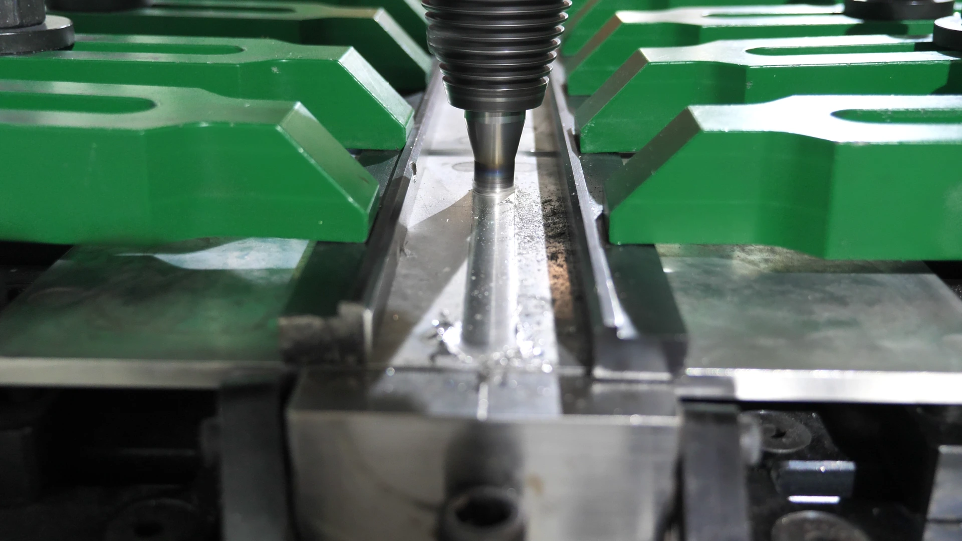
Friction Stir Welding (FSW) is a solid-state welding technique invented in 1995 by TWI (The Welding Institute). This method uses a rotating tool to generate heat through friction plasticizing materials to be welded. The tool then mixes the materials to create a homogeneous, high-quality welds.
The quality of the weld heavily depends on the welding parameters used. These parameters influence the heat generated, the mixing of materials, and the formation of the final weld. Optimal adjustment of these parameters is crucial to avoid defects such as porosity, bonding failures, or deformations, ensuring robust and durable welds.
The main FSW welding parameters are:
Choosing the FSW tool
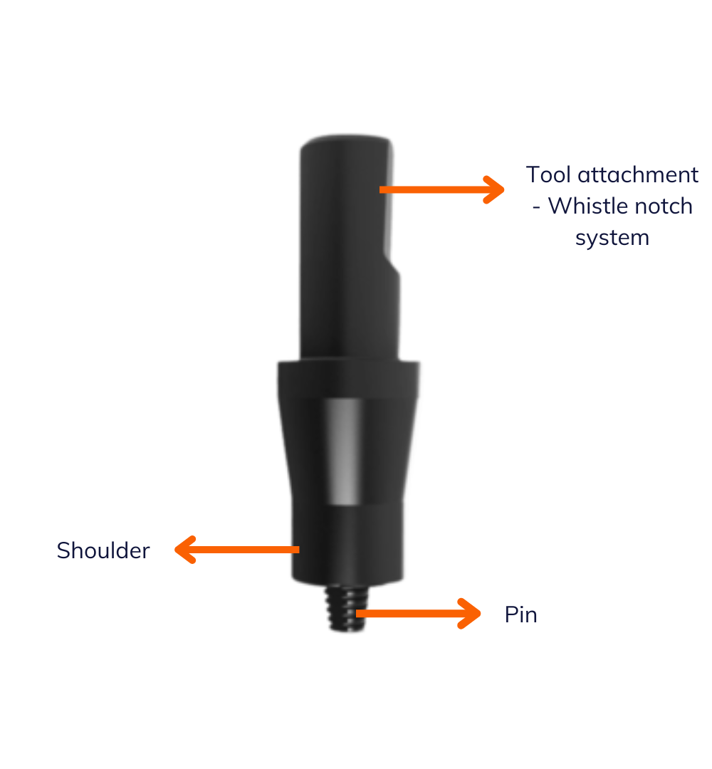
An FSW welding tool consists of two parts: the shoulder, which generates heat through friction, and the pin, which penetrates the materials and ensures their mixing.
The choice of the tool material depends on the materials to be welded and the welding conditions. Commonly used materials for FSW tools include steel (used for welding aluminium alloys) and carbide (used for copper and its alloys).
As you will have realised, the choice of FSW tool is very important, which is why we have dedicated a webinar to it. Don’t hesitate to watch the replay now: Replay Webinar – How do I choose my FSW tool for my application?

Rotation speed
Rotation speed is the speed at which the tool rotates around its axis. It is crucial for generating the heat necessary to plasticize the materials.
The choice of speed depends on several factors:
Incorrect rotation speed can lead to various defects:
Welding speed
The welding speed is the speed at which the tool moves along the weld joint. It determines the quality of the weld.
The choice of speed is influenced by the type of material to be welded – more difficult-to-weld materials like copper require slower travel speeds. Thicker parts require slower travel speeds to ensure proper heating of the materials.
Incorrect welding speed can lead to:
Forging force
Forging force is the pressure exerted by the tool on the materials to be welded. It is crucial for ensuring good tool penetration and effective material mixing.
The choice of forging force depends on the material type – harder materials require higher axial force – and the thickness of the part – thicker require higher forging force to ensure proper tool penetration.
If the forging force is too low, it leads to poor tool penetration, resulting in incomplete welds. If it is too high, it reduces the weld cross-section and its mechanical strength.
Defining FSW welding parameter
The spot method for material entry
What is the spot method?
The spot method is a technique used to introduce the welding tool into the material before starting your first weld. This method is very useful for determining the correct rotation speed and forging force, avoiding initial defects in the weld zone.

Principle of the method
The FSW tool is first positionned at a fixed point on the material linear displacement. The rotation of the tool generates frictional heat, plasticizing the material around the pin.
Practical application
To correctly apply the spot method in FSW, follow these steps:
Practical info:
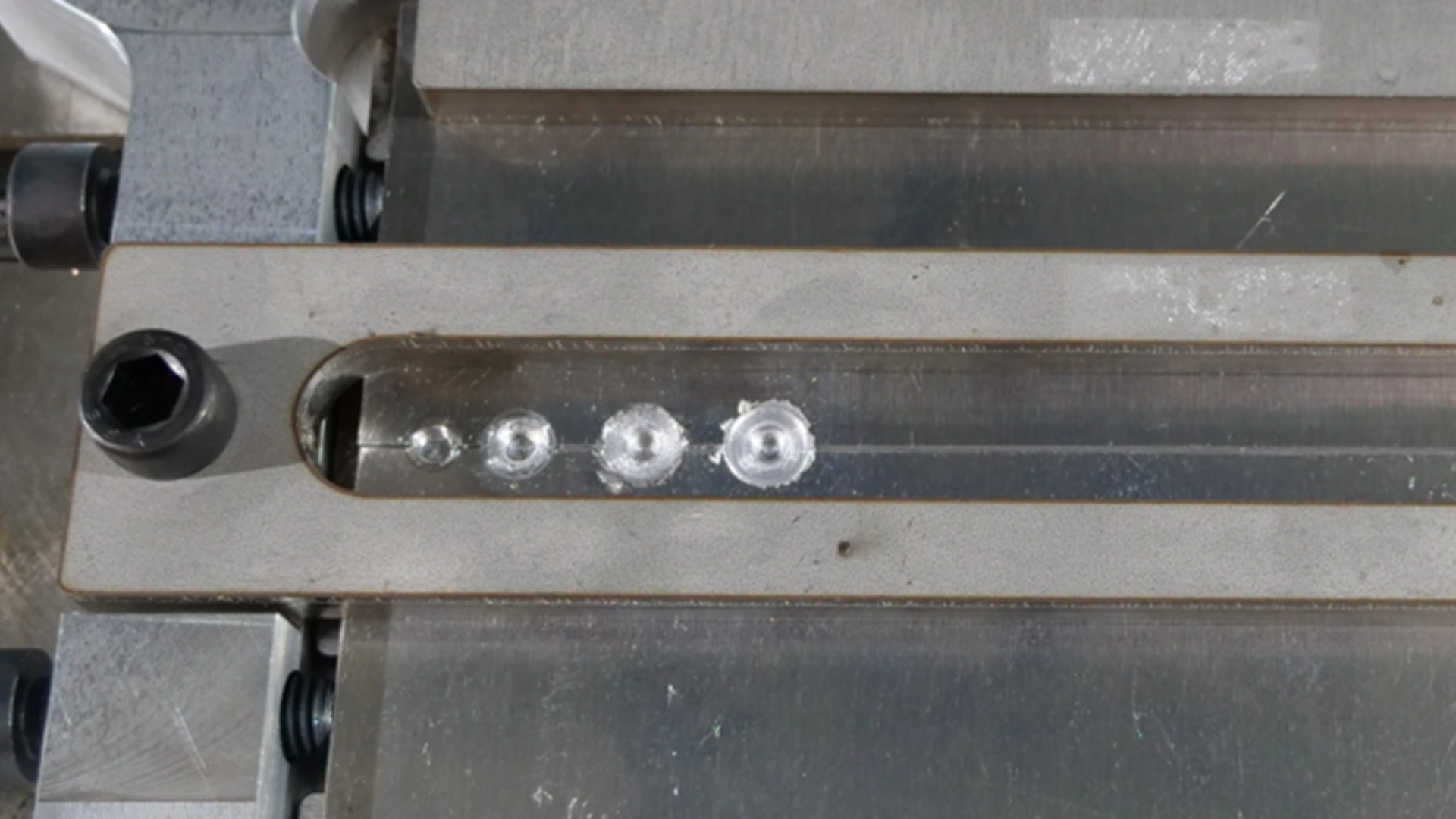
It’s important to go gradually and practice this point method several times to find the ideal rotation speed and forging force. Thos means applying a progressive force: the first attempt with little force, the second with a little more force and so on until you get the idea result.
When your first penetration of the material is complete, you should see a small indentation of the pin in the aluminium. As you can imagine, this isn’t enough, as we want the pin to enter the material completely. So, we need to increase the Z penetration of the tool.
You need to increase the Z penetration of the tool until you can clearly see the imprint of the shoulder of the FSW on the surface of your workpiece.
First weld lenghts and visual inspection of FSW welds
Performing the first weld beads
The first weld lengths are used to test and adjust the welding parameters before welding the entire part. They help identify and correct potential defects early on. Adjust the welding speed based on the tool size and rotation speed.
Here is an exemple of preliminary test setup recommended by our experts:
These tests make it possible to check the quality of the FSW weld, adjust the parameters accroding to the initial observations and thus minimise the risk of defects in the final part.

Visual inspection of FSW welds
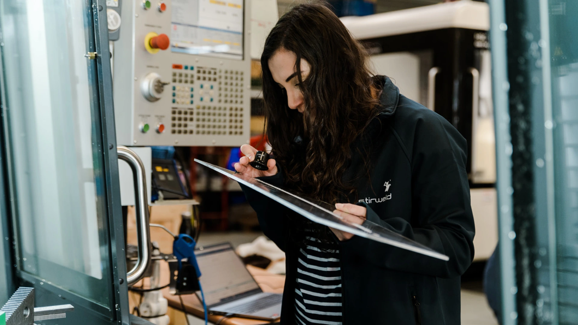
After performing the first weld lenghts, a visual inspection is done to evaluate the weld quality, determining if it was too hot, too cold, or at the right temperature. This is influenced by the rotation speed and travel speed.

In FSW, different types of defects can appear depending on the heat generated during welding:
To facilitate the definition of these welding parameters, it is very useful to measure the temperature in real time during the welding operation using a tool holder equipped with a temperature sensor.
Destructive characterization and adaptation of FSW welding parameters
Destructive and non-destructive control in FSW welding
Quality control of FSW welds is essential to ensure the reliability and performance of welded structures in various industrial applications. To ensure FSW welds meet quality and safety standards, rigorous controls are necessary, using destructive and non-destructive methods to evaluate weld integrity.
Destructive controls, such as those conforming to ISO 25239 or AWS D17.3 standards, pressure tests, and fatigue tests, provide an in-depth analysis of the internal structure and mechanical strength of the welds, althought they involve partial or total destruction of samples. Non-destructive technique, such as visual examination, ultrasonic inspection, X-ray radiography, X-ray tomography, dye penetrant testing and eddy current testing, detect internal and surface defects without damaging the inspected parts.
Adaptation of FSW parameters
After quality control of the initial welds, the welding parameters can be adjusted based on the obtained results.
If wormholes are present, reduce the rotation speed or increase the forging force to improve plasticization.
If there is porosity in the weld, adjust the welding speed and rotation speed to balance heat generation and material mixing.
If there is insufficient penetration, adjust the forging force or pin length.

Thus, the success of an FSW welding operation largely depends on mastering its parameters. By correctly understanding and adjusting the tool choice, rotation speed, welding speed, and forging force, welding professionals can avoid common defects and ensure optimal results.
The methodology explained in this article, including the spot method for material entry, performing representative initial lengths, visual inspection, and destructive and non-destructive characterization, provides a clear roadmap for determining and optimizing FSW welding parameters. By applying these techniques, welders can improve the quality of their welds, meet technical requirements, and ensure customer satisfaction.
Ready for your first welds?
Do not wait to apply these tips and improve or start your FSW welding processes. For more information and advice on setting optimal parameters for your part, contact us and receive advice from our experts.

