
Copper cold plates: which joining process to prioritize among FSW, vacuum brazing, and laser?
Liquid cold plates (LCPs) are critical for thermal management in high-power electronics (data centers, telecom equipment, HPC GPUs, etc.). Choosing the optimal joining process for copper cold plates can impact thermal performance, mechanical reliability (leak-tightness), production speed, and cost.
This article compares Friction Stir Welding (FSW), vacuum brazing, and laser welding for copper cold plate assembly, and provides design-for-manufacturing (DFM) guidelines for each.
Key differences between FSW, brazing and laser welding for copper cold plate joining
Joining copper cold plates can be done using three main processes: Friction Stir Welding (FSW), vacuum brazing, and laser welding. Each method has distinct impacts on thermal conductivity, leak-tightness, mechanical strength, and design flexibility. The following sections outlines their key differences.
Friction Stir Welding: a solid-state process for ultra-reliable copper joints
Friction Stir Welding (FSW) is a solid-state process: a rotating tool plunges into the joint between plates, plasticizing but not melting the copper, and “stirs” the interface into a forged homogenous weld. FSW has been rapidly adopted for aluminum cold plates in EV and data center markets due to its reliability and is now being applied to copper cold plates.
FSW solid-state process results in a joint with no filler metal and minimal defects: tensile strength often close to the base metal, and essentially zero internal voids. Consequently, the joint exhibits excellent thermal conductivity (since it’s just solid copper continuity) and perfect leak-tightness. FSW leads to ~50% higher stiffness than a brazed cold plate, reducing pressure distortion and resulting in less stress on electronic components. The trade-offs are that FSW is mainly suited to relatively simple joint geometries and requires rigid fixturing and tool access along the entire weld path. FSW is a mature process for aluminum and copper.
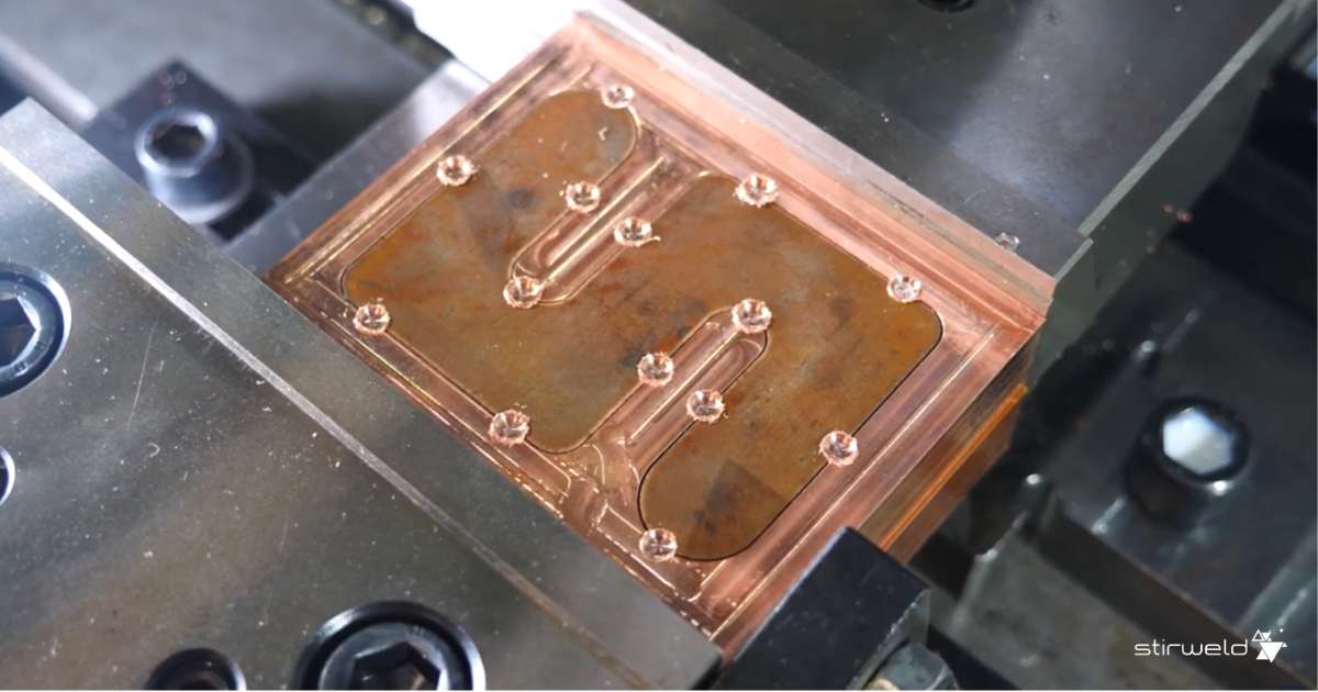
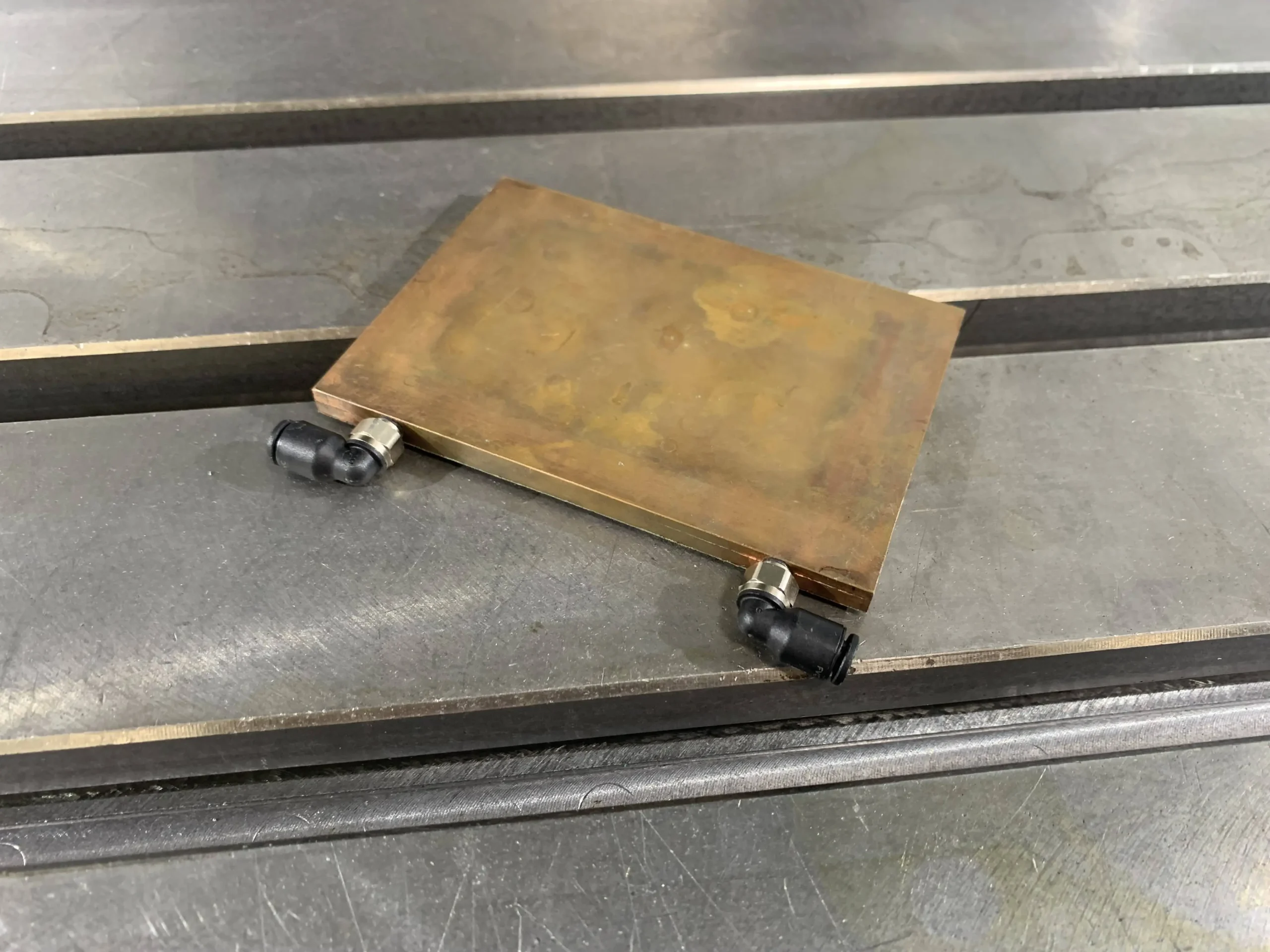
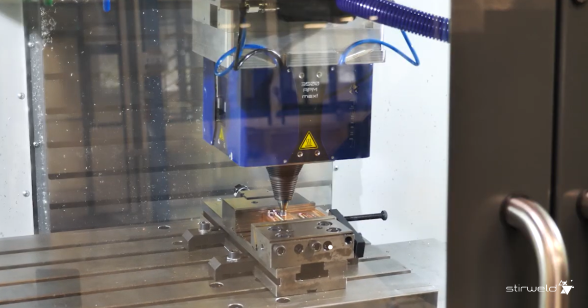
The following video provides a practical demonstration of Friction Stir Welding applied to a copper cold plate. This example helps visualize how the solid-state process works in real conditions and why FSW can achieve high-quality, leak-tight joints on copper.
Vacuum brazing: a mature process for complex copper assemblies
Vacuum brazing is a traditional, widely used method for cold plate assembly. Copper (or plated copper) parts are joined by heating them in a vacuum furnace with a filler alloy (often a copper-silver or phosphorus bronze alloy for copper parts) that melts and flows via capillary action to bond the pieces.
Vacuum brazing can join very complex assemblies in one operation: for example, a base plate with dense internal fins or multiple components, which is not feasible with a single FSW or laser seam. Vacuum-brazed joints generally offer good strength and thermal contact, but because a softer filler metal is involved, joint strength and fatigue resistance may be slightly lower than a wrought weld, and thermal conductivity at the joint is somewhat reduced compared to pure copper.
A key consideration is reliability: vacuum brazing inherently carries a risk of micro-voids or incomplete filler coverage, which can create leak paths or reduce pressure capability. Over time and thermal cycling, these micro-defects can propagate; thus, while vacuum brazing yields strong joints, it has a non-zero leak failure rate in the field (e.g., microscopic braze defects causing leaks after many cycles).
Nonetheless, vacuum brazing is a highly mature process with decades of use in aerospace and electronics cooling; many design standards and experienced suppliers exist. Finally, high vacuum brazing temperatures can induce copper yield/strain reduction, degrading plate stiffness and increasing pressure distortion, which results in more stress on electronic components.
Laser welding: a precise fusion process for copper cold plates
Laser welding uses a concentrated laser beam (fiber lasers for industrial welding) to fuse the copper plates along a seam. This is a fusion welding process: the copper at the joint is melted and resolidifies, forming a metallurgical bond. Laser welding is precise and fast; a focused laser can scan a seam at 1 m/min, creating a narrow weld with minimal overall heat input.
In copper cold plates, laser welding is emerging to seal simple lid-to-base joints, especially for smaller plates (50×50×3 mm). Modern high-power lasers (especially in the green wavelength) can weld copper despite its high reflectivity. Like FSW, laser welds use no filler metal, so the interface is pure copper, offering excellent thermal performance if the weld is defect-free. Only a narrow seam is heated and cooled rapidly, producing a small Heat Affected Zone (HAZ) without annealing the entire part.
However, laser welding copper presents challenges: copper reflects much of the IR laser energy and conducts heat quickly, making full penetration without defects difficult. Pores or tiny cracks can form if parameters aren’t perfectly controlled, compromising strength and leak-tightness. Additionally, laser welding is mainly limited to continuous perimeter seams or simple attachments and cannot join complex internal features, unlike brazing which can bond multiple interfaces at once.
In summary, laser welding is valued for its speed and precision, and advancements (such as fiber lasers, improved beam quality, and better process control) have made copper welding feasible. But it requires careful control to achieve weld quality comparable to FSW; otherwise, defects like porosity can reduce reliability under pressure. The technology is mature in general industry, but for thick copper cold plates it remains somewhat specialized due to copper’s challenges.
FSW RESSOURCE
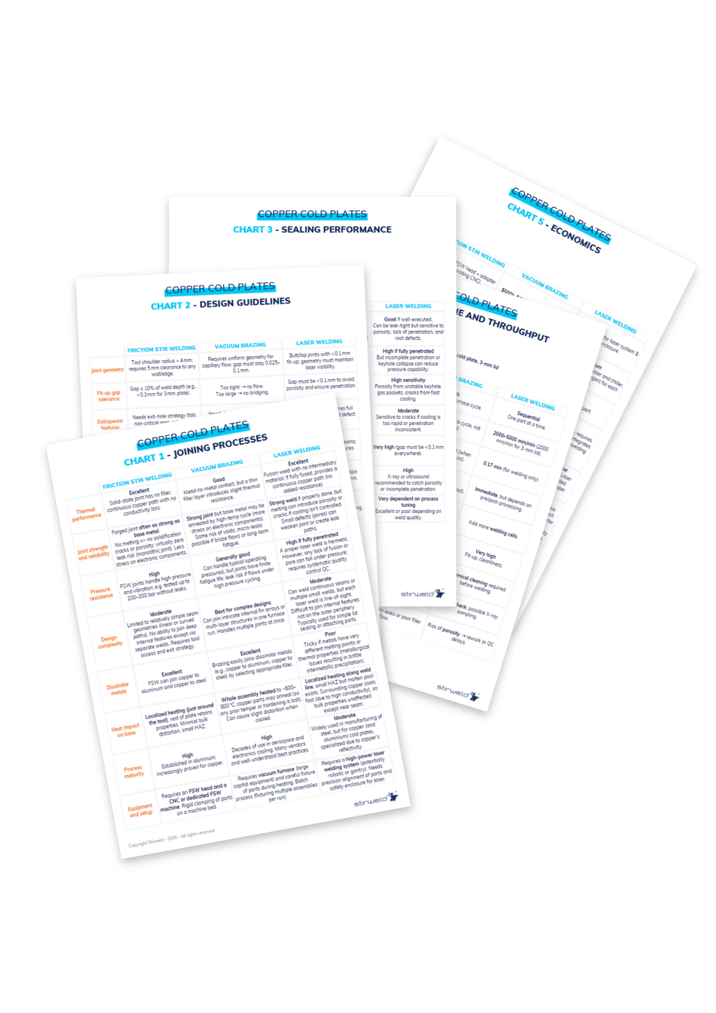
Download the 5 comparison charts for copper cold plate joining decisions
This free resource benchmarks FSW, vacuum brazing, and laser welding to support your process selection.
The five copper cold plate charts cover joining processes, design guidelines, sealing performance, takt time and throughput, and economics.
How to design copper cold plates based on the joining process
DFM (Design for Manufacturing) rules specific to FSW, vacuum brazing, and laser welding are presented below. The guidelines cover joint geometry constraints, spacing, tooling access, and preparation steps, with examples from real-world applications.
Design guidelines for FSW
Material preparation
Although FSW tolerates oxides better than laser welding, thanks to its mechanical disruption of surface layers, joint surfaces should still be free of heavy oxide or contamination to ensure consistent weld quality.
Joint geometry & tool clearance
FSW requires careful attention to joint geometry. The FSW tool shoulder, which has a minimum radius of about 4 mm, cannot approach edges or vertical features too closely. A spacing of 5 mm between the weld line and any raised geometry ensures that the tool can operate without collision. Fit-up is equally important: interface gaps must stay below 10% of the weld penetration, meaning that for a 3 mm plate, the gap should remain under 0.3 mm.
Exit hole management
Because FSW leaves a keyhole at the point where the tool retracts, the design must incorporate a strategy to manage this feature. The exit point can be placed in a non-critical zone, positioned on a run-off tab that will later be machined off, or eliminated using a retractable-pin FSW head.
Fixturing & support requirements
Rigid support beneath the weld path is essential. The part must provide a continuous bottom surface whose width corresponds to the tool diameter. For long welds or complex geometries, temporary FSW tack points or automated clamping may be used to stabilize the assembly before the main welding pass.
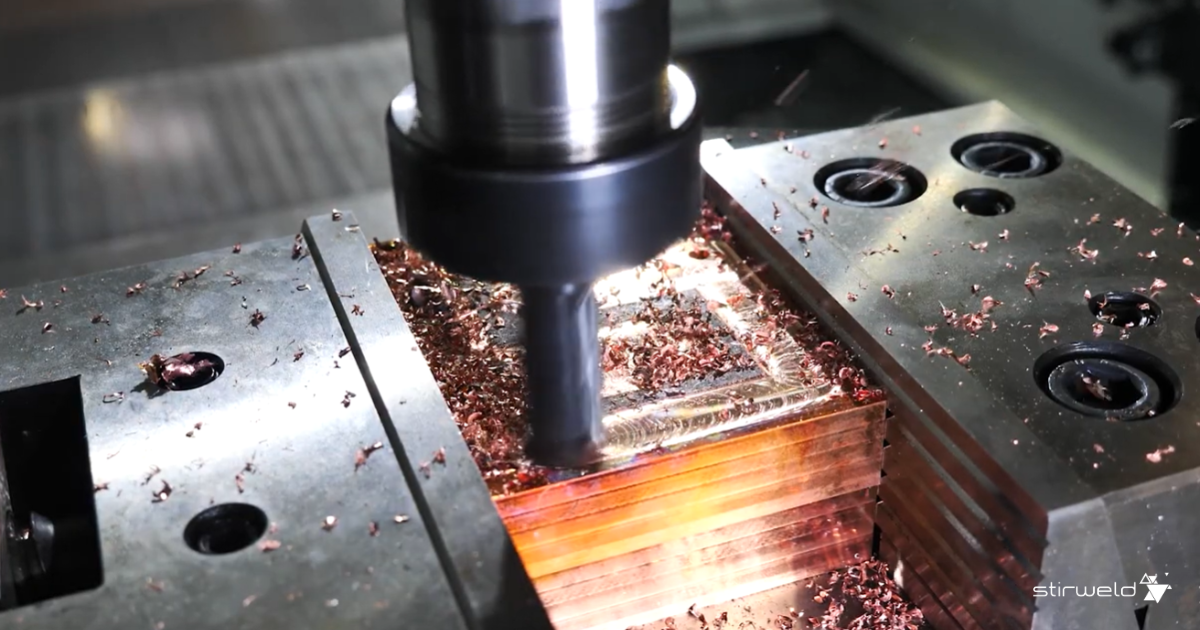
Post-weld machining
FSW can produce slight flash or burrs around the weld. The design should therefore allow a machining allowance of around 0.5 mm so that these minor imperfections can be removed, typically with the same CNC machine using an automatic tool change.
Design guidelines for vacuum brazing
Joint clearance & capillary flow
Vacuum brazing relies on capillary action at 600-800 °C to draw molten filler (typically a copper-silver or phosphorus alloy) into the joint. To enable reliable flow, the joint gap should generally be kept around 0.025-0.1 mm, depending on the alloy. If the clearance is too large, the filler will not bridge consistently; if it is too tight (near zero), the alloy cannot flow. Surfaces with large areas should therefore be specified with tight flatness and overall tolerance to maintain the intended gap.
Filler material & placement
For copper cold plates, filler is commonly provided as silver brazing foils or preforms placed around the perimeter. The design can integrate small grooves or pockets to position the alloy, or establish a lap region that sandwiches a filler foil at the interface. This ensures the filler is present where needed and supported during the furnace cycle.
Preventing filler entrapment & channel blockage
Because molten filler can run into fluid channels, designs should anticipate potential braze run-out. A practical countermeasure is to add braze-stop features, such as a small 0.05 mm step along the periphery. When internal fins or other features are present, it is also important to provide vent holes or paths so that the atmosphere and any trapped gases can escape rather than redirecting the molten alloy into unintended areas.
Thermal symmetry & distortion control
The entire assembly is heated and cooled in the furnace, so differences in section thickness near the joint can lead to differential expansion, gaps, or distortion. A design that maintains uniform section thickness around the joint area helps control these effects and supports consistent filler distribution.
Cleanliness requirements
Joint surfaces should be clean of oils and oxides, and any non-compatible plating or coating must be avoided at the interface. When flux is used in non-vacuum brazing contexts, the joint should be designed to allow complete removal of flux residue, avoiding blind spots where residues could be trapped. In all cases, accessibility for cleaning is an essential consideration at the design stage.
Accommodating braze alloy properties
Copper cold plates typically use BCuP (copper-phosphorus) or BAg (silver-based) fillers, which have lower strength than copper. To achieve the required joint performance, the design should provide sufficient brazing surface area, leveraging geometry rather than relying solely on filler strength.
Joining dissimilar metals
When dissimilar materials are involved, different coefficients of thermal expansion (CTE) can cause parts to slip or create gaps during the thermal cycle. The design must therefore account for relative movement so that joints remain aligned and gap control is preserved through heating and cooling.
Machining allowance
Because brazing can introduce part distortion, the design should include provision for post-braze machining to restore critical dimensions and ensure final fit and seal integrity.
Design guidelines for laser welding
Joint type & fit-up requirements
Laser welding of copper cold plates typically uses butt or lap joints. A butt joint requires an extremely tight fit, with a gap below 0.1 mm, to ensure proper penetration and weld quality. Lap joints are more common, but they also require a gap of less than 0.1 mm to avoid porosity. Because heating during welding can distort the lid and open the joint, the design must include appropriate clamping to keep the lid firmly pressed onto the cold-plate housing throughout the weld.
Gap tolerance
To avoid porosity and ensure full penetration, the maximum allowable gap is 0.1 mm. Maintaining this tolerance is critical, as defect formation increases sharply once the gap exceeds this limit.
Joint accessibility
The laser beam must have direct visual access to the entire weld seam. This line-of-sight requirement is a fundamental constraint when shaping the joint interface and surrounding features.
Thickness & penetration considerations
Laser welding can achieve full penetration through a lid up to 3 mm thick. For thicker components, the interface should incorporate a scarf joint or a reduced cross-section to keep penetration achievable. Maintaining uniform thickness along the weld line also helps ensure consistent laser parameters and stable weld quality.
Material & surface preparation
Copper surfaces must be extremely clean and oxide-free; solvent cleaning is recommended. Any contamination can cause porosity during the molten phase. Coatings and abrasive treatments that embed particles-such as sandpaper-should be avoided. For best results, welding-grade alloys such as C101/C102 (oxygen-free copper) are preferred over C110.
Fixturing & alignment
A close-fitting fixture or clamping system must maintain zero gap between the lid and the housing throughout welding. Because the laser spot is small (around 1 mm), the fixture must ensure a positioning accuracy better than 0.2 mm to keep the beam precisely aligned with the joint.
Sealing performance under pressure: which joining process unsures leak-free cold plates
Sealing performance is a critical aspect of copper cold plate reliability, especially when assemblies operate under high internal pressure or repeated thermal and mechanical cycling. The joining method directly influences leak-tightness, susceptibility to defects, and long-term durability. The sections below compare how FSW, vacuum brazing, and laser welding perform in terms of pressure resistance and leak-free operation.
FSW: sealing performance and leak-tightness
Friction Stir Welded joints in copper are essentially forged metal and FSW welds have sustained very high pressures (200 bar, 2900 psi). Moreover due to the solid state process, no porosity or leak is observed (if done correctly) by helium leak tests. Additionally, FSW joints have excellent fatigue resistance (no crack under pressure cycling or vibration). That’s why FSW is preferred in extreme environment such as aerospace.
Vacuum brazing: risks of leaks and inspection requirements
Vacuum brazed joints has inherent risks of minor defects: small voids, incomplete fillets, or flux entrapment (if flux were used) can create leak paths. A brazed joint reliability depends on process control: proper clearances, alloy flow, and inspection. The occurrence of micro-leaks in brazed cold plates is not zero. Over time, differential expansion or corrosion can worsen an incomplete brazed joint and cause a leak in service. A properly filled brazed joint often has a fillet that can be visually inspected but internal sections cannot be easily checked and requires a X ray quality control.
Laser welding: leak-tight potential and defect sensivity
Laser Welded joints, if properly executed, can be leak-tight. However, a laser weld can suffer from porosity (gas pockets in the weld metal) due to low copper viscosity at high temperature and the instability of laser keyhole. Those pores, if interconnected or if on the surface, can cause a leak. Also, if the laser didn’t penetrate the entire thickness everywhere (perhaps due to fit-up variation), there could be an unmelted line at the joint root of the joint. Another factor is the copper sensibility to crack under fast cooling. So the quality control for laser welds is mandatory: ideally use X-ray or ultrasound.
Production considerations: takt time and throughput
Production throughput varies significantly depending on the joining method used to seal copper cold plates. Factors such as linear welding speed, batch processing time, and pre/post-processing steps directly influence takt time and overall manufacturing efficiency. Here is an example of a small plate (50×120 mm) with a 3-mm thick lid as a baseline.
FSW: takt time and process characteristics
Friction Stir Welding (FSW) is a sequential process, one weld (one part) at a time. Welding speed for copper is from 100 to 400 mm/min depending on weld penetration. For 3-mm thick lid, the welding speed is 300 mm/min, leading to a takt time of 1,1 minutes.
Vacuum brazing: batch cycle time and furnace throughput
Vacuum brazing is a batch process with a significantly longer cycle time per batch: pumping down, ramping up temperature, holding at brazing temperature, then cooling down. A full cycle can take commonly 3 hours total. The advantage is that many parts can be brazed in one batch – dozens if the furnace is large and fixtures are stacked. By brazing 60 cold plates in a 3-hour run, that leads to 3 minutes per plate, not counting loading setup. But the latency from start to finish for a batch is hours. If one part is missed in the last batch, you wait 3 hours for the next.
Laser welding: cycle time and pre/post-processing requirements
Laser welding is a sequential process per machine (like FSW). Welding speed for copper is from 2000 to 5000 mm/min depending on weld penetration. For 3-mm thick lid, the welding speed is 2000 mm/min, leading to a takt time of 0,17 minutes. However, the takt time can be impacted by extra operations: chemical cleaning before welding and QA check after each weld.
Post-process requirements for each joining method
FSW usually needs minimal finishing (can be done in the same CNC immediately). Brazing might need leak testing of each part and possibly straightening if any warp. Laser might require a visual inspection or maybe an X-ray sample inspection.
FSW RESSOURCE
Download the 5 comparison charts for copper cold plate joining decisions
This free resource benchmarks FSW, vacuum brazing, and laser welding to support your process selection.
The five copper cold plate charts cover joining processes, design guidelines, sealing performance, takt time and throughput, and economics.
Economics of joining copper cold plates: CAPEX, OPEX, training and production integration
The economic aspects and deployment constraints of each joining process: capital investment (CAPEX), operating costs (OPEX), required skills, and integration into manufacturing workflows-vary significantly between FSW, vacuum brazing, and laser welding.
FSW cost analysis: CAPEX, OPEX, training and integration
FSW investment cost (CAPEX) and equipment requirements
FSW has a moderate investment cost, (≈ $100k )especially when using a retrofit head on an existing CNC machine. Fixturing costs are low because FSW does not require extremely accurate clamping.
FSW operating costs (OPEX) and maintenance
FSW has low operating costs.
The process uses no filler metals, no shielding gases, and consumes energy equivalent to a CNC’s spindle motor. The main consumable is the FSW tool for copper welding, with lifetimes ranging from 100 to 500 m of weld length in copper depending on parameters and alloys. Maintenance is straightforward: inspecting the force control system, replacing tools, and maintaining elements such as the backing anvil or cooling system.
FSW training and skill requirements
FSW required training is minimal. Operators familiar with CNC machining can be trained to run FSW in two days, with no special safety hazards (no lasers, high voltage, or flames).
FSW integration into existing facilities
FSW integrates very easily into a CNC workflow.
An FSW head fits standard spindle interfaces (HSK63, BT40, etc.) and adds almost no extra footprint except for a small chiller(1 × 1 m). No fumes, UV, or noise require special facilities. The built-in overload protection (“piston system”) prevents damage to the CNC.
Vacuum brazing economics: equipment cost, operating cost, skills and facility requirements
Vacuum brazing investment costs (CAPEX) and furnace equipment
Vacuum brazing requires a high-vacuum furnace, a major capital investment typically $500k to over $1M, depending on size and capability. Installation requires significant infrastructure: high-power electrical supply, cooling water, gas lines, and substantial floor space.
Vacuum brazing operating costs (OPEX) and maintenance needs
OPEX is high, driven by large energy consumption (heating the furnace mass to 750-800 °C), vacuum pump operation, and costly filler alloys (silver-based braze alloys can cost several dollars per part).
Maintenance includes vacuum pump servicing, chamber cleaning (condensed braze vapors), calibration, and periodic heater replacement. If flux is ever used (outside vacuum brazing), flux cleaning adds complexity. Yield loss can also be significant: leaking or defective plates may lead to 5-30% scrap.
Vacuum brazing training and process skill requirements
Vacuum brazing is a metallurgical process, requiring expertise in alloy selection, fixture design, and furnace cycle definition. Developing a reliable recipe typically requires a metallurgist or welding engineer.
Vacuum brazing integration into production facilities
A furnace is a standalone asset, separate from machining operations.
Workflow becomes segmented: parts must be cleaned (ultrasonic cleaning), fixtured, loaded into the furnace, and later inspected. The furnace area typically requires cooling water supply, gas lines, safety measures for hot surfaces, and dedicated floor space.
Laser welding economics: investment cost, operational cost, training needs and production integration
Laser welding investment cost (CAPEX) and laser equipment
A copper-capable industrial laser system (4-6 kW fiber laser) with automation costs $250k-$500k. Installation requires adequate power supply, cooling water, and shielding gas systems, along with a laser-safe enclosure.
Laser welding operating costs (OPEX) and maintenance
Laser welding OPEX includes electricity for the laser source and chiller, shielding gas consumption, and periodic maintenance such as replacing optics. Safety systems (interlocks, enclosures, certification) also add operational overhead.
Laser welding training and process skill requirements
Laser welding requires trained technicians or engineers, primarily due to laser safety (Class 4) and the precision required to tune welding parameters (power, focus, speed, pulse).
Copper’s reflectivity and process sensitivity often require an experienced welding engineer to establish stable parameters
Laser welding integration into production facilities
Laser welding is integrated as a dedicated station in the production flow.
After machining and cleaning, parts are transferred to the laser cell. The primary facility requirement is a Class 4 laser-safe enclosure, and depending on local regulations, ventilation for metal vapor may be necessary.
Synthesis of the comparative guide for copper cold plate joining methods
The optimal joining process for copper cold plates depends on a balance of technical requirements (thermal performance, pressure sealing, geometry) and practical considerations (available equipment, volume, budget).
Working on a copper cold plate project?
Our experts support you from testing and validation through full industrial deployment.