
How to remedy deformation of a Friction Stir Welded part?
Whatever the welding technique used, an unavoidable phenomenon distorts the welded parts to a greater or lesser extent. Although this undesirable effect is less pronounced when welding is carried out using Friction Stir Welding (as the temperature is lower), it does occur (FSW structures are 2 times less distorted than arc welding). Fortunately, several precautions and techniques can be taken to limit distortion and avoid its consequences.
Why are Friction Stir Welded (FSW) parts prone to distortion?
Deformations caused by Friction Stir Welding are thermal in origin and can be accentuated by the characteristics of the workpiece and the weld.
The impact of heat generated by the FSW tool
In Friction Stir Welding (FSW), the hottest zone of the weld is between the shoulder and the pin, both of which are components of the tool. At this precise point, 60-80% of the material melting point is generally reached, for example 400-550°C for aluminum, depending on the alloy. This temperature is reached just as the tool passes through. The further away from this point, the colder the part. As a result, temperature differences between multiple zones on the part create thermal stresses during cooling, which are then transformed into deformations when the part is unclamped.

Contrary to popular belief, the deformations resulting from FSW are not due to the force exerted by the tool during welding, but to the heat it generates. In other words, they result from residual welding stresses generated by temperature gradients in all directions on the workpiece. All these high temperature differences generate different stresses in different areas of the workpiece, creating deformations as it cools.
However, Friction Stir Welding is less subject to distortion than other welding techniques, since heating is essentially localized at the tool, and the temperature reached is lower. In the case of fusion welding, for example, the temperature reached is higher (1000°C for MIG and 2000°C for laser welding), and the heat is applied over a much wider area than just the diameter of the FSW tool (mainly for arc welding).
Characteristics that favour deformation of FSW-welded parts
The extent of deformation of Friction Stir Welded parts varies according to these two criteria:
How to detect deformation in a welded part?
Deformations are measured using metrology tools. They are not necessarily visible to the naked eye, as they can be as small as 0.2 mm. They can, however, be flagrant, measuring several centimetres in length, in which case they take on the appearance of a banana.
Whether they are more or less pronounced, deformations generally appear in the same way, in the same direction. In practice, the center of the part is firmly pressed against the support on which it is placed and corresponds to its lowest point. On the other hand, the corners of the part tend to rise. The value of the deformation, also known as the sag, corresponds to the difference between two points on the part: the lowest and the highest.

What actions can be taken to remedy the deformations caused by Friction Stir Welding?
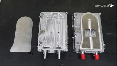
Because of their function, some parts cannot tolerate the slightest deformation. This is the case with cold plates, which are used to cool electronic components and must be very flat to ensure perfect contact.
To reduce the distortion generated during Friction Stir Welding, and cancel out its effects, there are several techniques that can be applied individually or in combination, during the three stages of the assembly process:
FSW RESSOURCE
FSW Memo: 13 actions to remedy deformations of a FSW welded part.
To get your free FSW resource, fill in the form below.
Actions that can be taken before welding
Reduce the weld length during the design phase
As explained above, the action of the FSW tool generates heat, which is the source of distortion. Limiting the length of the weld reduces the heat input applied to the part, and therefore the distortion.
Use the smallest possible welding tool
The F-AA model designed by Stirweld is an FSW tool with a small diameter. This reduces the heat input during welding.
Consider stiffening the part, if technically possible
For example, small stiffeners placed between two metal plates stiffen the whole, which will limit deformation during welding. This is particularly relevant for welding castings, where the manufacturing process allows these stiffeners to be created directly on the part. For machined cold plates, these stiffeners can be milled into the cooling channel, thereby improving thermal performance.
Pre-deforming the part
The deformation of a part welded by FSW is very difficult to estimate but is particularly repeatable. It can therefore be pre-deformed in the opposite direction, so that it regains its flatness during welding. To achieve this, clamping tools are used to hold the part in the desired position.

Provide a maximum excess thickness of one millimeter, equivalent to the expected deformation (and remove it after welding by milling)
This technique, anticipated at the design stage, is finalized after welding, with a machining step. By experience, an FSW expert can estimate the extent of the deformation, depending on the dimensions of the part to be welded, the length of the weld and the welding tool used. This trick should be limited to a small allowance: increasing it could increase the welding penetration required, and thus the size of the welding tool and the amount of deformation.
Actions that can be taken during welding
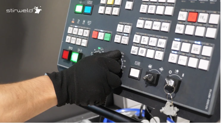
Adapt welding parameters
Good adjustment of welding parameters helps reduce heat (for example a high welding speed to reduce the energy input).
Preheat the room
This very common practice in fusion welding can also be applied to FSW. It involves placing the workpiece in an oven (or other method) beforehand, then removing it once it has reached the desired temperature. Welding then takes place on the still hot part. In this way, the temperature difference between the welding area and other areas of the part is smaller, which limits distortion.
Adapt the welding sequence: the back step method
Rather than welding all at once, this method involves welding in several stages to distribute the heat as evenly as possible. In this way, the deformation created by expansion and shrinkage is kept under control. In concrete terms, several small welding beads are made one after the other, always moving towards the bead just welded.

Actions that can be taken during welding
Machine the excess thickness voluntarily added during part design
If this 0 to 1 mm excess material, corresponding to the value of the deformation, was planned at the design stage, simply remove it by milling to correct the flatness defect in the welded part.
Weld the reverse side in full material, using the same welding sequence
This technique is equivalent to hot shrink straightening, commonly used in conventional welding. But in FSW, the method consists in turning the part over so that the tool makes a “false weld” on the back of the area that has been welded, over the entire weld path or just a few sections. This passage can be made very precisely, thanks to the welding program initially designed. However, this method is not applicable to all types of part, particularly casting housings, as it requires a clear space for the tool to pass over this back face.
Mechanically straighten the part
This option is designed for parts that have undergone severe deformation during welding and depends on their thickness. The thinner the part, the less rigid it is, and the more likely it is to deform:
Use stress-relieving heat treatment
This technique involves clamping the welded part, then placing it in an oven. By applying the right temperature and time, deformation can be reduced. For productivity reasons, the use of this option depends on the sector of activity. For example, it can be used in the aerospace industry.
Apply compressive stresses
Since the deformations of a welded part result from tensile stresses, it is possible to cancel them out by means of opposing forces, i.e., compressive stresses:
Some precautions to be taken due to deformation caused by welding
Depending on the characteristics of the part to be welded, a few best practices are recommended:

How can Stirweld help you overcome distortion?
Dedicated exclusively to the revolutionary technology of Friction Stir Welding, our team has many years’ experience in this field. Led by Laurent Dubourg, a world expert in FSW with over 20 years’ experience, our IWE® (International Welding Engineer) certified engineers bring their expertise to bear on a daily basis, helping manufacturers in a wide range of sectors to bring their projects to a successful conclusion. Success depends on mastering the phenomenon of distortion!
Would you like to KO the distortion?
Our design and prototyping department can study your project, then make prototypes to define the most appropriate method for producing parts that meet your specifications perfectly.