


Effect of welding parameters on microstructure and mechanical
properties of AA7075-T6 friction stir welded joints
F.Gemme1, Y.Verreman1, L.Dubourg2 and P.Wanjara2
1Mechanical Engineering Department, Ecole Polytechnique de Montréal, Montréal, Canada
2Aerospace Manufacturing Technology Center, Aerospace Research Institute, National Research Council, Montreal, Canada
The effects of advancing speed and rotational speed on the microstructure and the mechanical properties of friction stir welded 7075-T6 aluminium alloy sheets were studied. The fatigue strength of sound joints was measured and compared to tensile testing results. Macrographs and microhardness maps were carried out to reveal the microstructure transformations. Fractographic observations were made to identify the failure mechanisms. The effects of welding parameters on the fatigue strength are discussed in terms of welding pitch k (mm/rev) and heat input (J/mm). At a high welding pitch, crack initiation at the root of the circular grooves left by the tool on the weld surface is the most detrimental failure mechanism. As the size and the depth of the grooves are related to the welding pitch, the fatigue strength increases when the welding pitch is reduced. However, when the heat input is excessive, the failure is caused by sub-surface defects produced after ab normal stirring and/or by softening of the heat-affected zone. Lateral lips on the weld surface edges also have an effect on the fatigue strength for intermediate welding pitch values.
Key-words: 7075 aluminium alloy; fatigue; friction stir welding; heat input; process parameters; welding pitch.
1 – Introduction
Friction stir welding (FSW) is a solid-state joining process that has become a viable manufacturing technology for the structural assembly of metallic sheet or platematerials in many industrial applications. Moreover, the process has been recognized as a potential joining technique for high strength aluminium alloys with low weldability, such as crack sensitive grades of the 2XXX, 6XXX and 7XXX series. As the process utilizes low energy and achieves solid-state joining, consumables commonly required for conventional fusion welding of aluminium alloys, such as filler wire to adjust the chemistry of the weldment (lower crack sensitivity) and shielding gases to protect the molten pool, are not needed in FSW1. The FSW process principles are well described in a review by Bhadeshia2. As shown in Fig. 1, a rotating cylindrical, shouldered tool with a pin on its extremity is plunged at the interface between two butted sheets or plates until contact is made between the shoulder and the top surface of the workpiece. A downward force is applied to maintain sufficient friction in order to induce material flow. Heat is generated by friction and plastic strain. A translating movement is then applied to perform the weld by stirring the softened material from each workpiece. The combination of large plastic strain and elevated temperature has an important effect on the microstructure of the base material. The material flow around the welding tool Fig. 1. The friction stir welding process results in a region called the nugget where small recrystallized grains appear. A thermomechanically affected zone (TMAZ), where grains are also strained but not recrystallized, is observed outside the nugget. In the heat-affected zone (HAZ) outside the TMAZ, the grains shape remains unchanged. The precipitation state is affected by elevated temperatures in these three regions3.
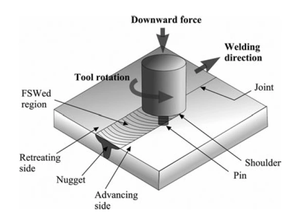
Figure 1 – The friction stir welding process.
The fatigue behaviour of welded joints is a very important issue for the design of aerospace and transport structures. The behaviour of butt welds under cyclic stress conditions has been studied in order to explore the possibility of using FSW as an alternative to fusion welding techniques. FSW produces joints of higher mechanical resistance than common fusion welding techniques. For example, the fatigue strength of 6082 aluminium alloy friction stir welded butt joints is higher than TIG and MIG-pulse butt welds of the same material4. Several investigations have been conducted in the last 10 years in order to have a better understanding of the fatigue mechanisms of crack initiation and propagation in FSW joints5.
A critical condition for good fatigue strength of FSW joints is the manufacture of an integral weld along the entire length of the structure. For butt joints, a primary consideration is the achievement of complete weld depth penetration to prevent a reduction in the cross-sectional area of the weld. The stirred zone can be insufficiently deep in the welded material thickness, resulting in a lack of penetration (LOP). This creates a root flaw at the bottom surface of the joint. The root flaw is considered as the most detrimental defect for fatigue strength of friction stir welded joints. It was shown that for aluminium alloy 7075, the fatigue strength of friction stir welded butt joints with root flaws can be as low as 10% of the basematerial fatigue strength6. However, it was also shown that the sensitivity to root flaws can change for different alloys or different hardening states7. The LOP defect can be avoided in two different ways. First, it is possible to remove a material layer at the bottom surface of the joint in order to eliminate root flaws. However, post-machining reduces the process productivity and is not suitable for thin sheets. In addition, post-machining of weld specimens may modify the state of residual stresses, which in turn may affect the fatigue resistance. Secondly, the pin length of the tool must be selected and positioned to allow material movement and coalescence at the root of the joint through the stirring action of the tool. The effect of the other welding parameters on the LOP defect occurrence has not been clearly demonstrated.
When the LOP defect is avoided, the most important factor influencing the fatigue resistance of FSW joints is the ratio between the advancing speed v and the rotational speed ω,7,8 also called the welding pitch k: k = v/ω.
A high welding pitch value leads to a ‘cold’ weld with insufficient material stirring may cause internal welding defects such as wormholes. The fatigue resistance of FSW joints can be enhanced by decreasing the welding pitch to reduce the occurrence of these ‘cold’ internal welding defects9. On the other hand, ‘hot’ welding conditions are obtained at low welding pitch values. In this case, excess flash on the weld sides and tearing of the weld surface can be observed. These defects are potential crack initiation sites and therefore can have a detrimental effect on fatigue strength. Although the welding pitch and the heat input are interrelated8, the individual effects of the advancing and rotational speeds on the resulting heat input may be different10.
FSW process parameters can be selected in order to avoid welding conditions that lead to ‘cold’ or ‘hot’ defects and produce sound joints11, 12. Inside this operating window, the welding pitch still has an effect on the fatigue behaviour of FSW joints in heat-treatable aluminium alloys, such as the 2XXX, 6XXX and 7XXX series. It was shown that for sound butt joints made in AA 6082, the fatigue strength is lower for welds manufactured with a low-welding pitch and therefore a high-heat input13. The failure was observed outside the welded joint in the softened HAZ due to precipitation coarsening. These results indicate that the operating window for heat-treatable alloys, in terms of fatigue resistance, is limited on the ‘cold’ side by the occurrence of internal welding defects and on the ‘hot’ side by the extent of the precipitate coarsening in the HAZ.
For non-heat-treatable aluminium alloys such as the 3XXX and 5XXX series, improvement in the high cycle fatigue resistance was reported for low values of the welding pitch, when the heat input is higher14. As for heattreatable alloys, the operating window is limited on the ‘cold’ side by the occurrence of welding defects. However, the quality of FSW joints can be improved by decreasing the welding pitch until a critical value when ‘hot’ defects, such as excess flash and tearing of the weld surface, are observed.
This paper presents a systematic study where the static and cyclic strengths of friction stir butt welds made of aluminium alloy 7075-T6 are measured for different values of the rotational speed and the advancing speed. The FSW process parameters are selected in order to ob-tain sound welded joints, i.e. without LOP root flaws or excess flash on the top surface. S-N data and fractographic observations are analysed with respect to the microstructure profile, the precipitation state and the surface topology of the welded joints. Failure mechanisms are identified for each case and the relationship between these mechanisms and the welding parameters is discussed.
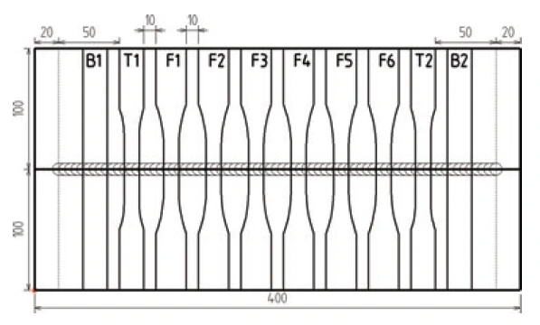
Figure 2 – Drawing of the welded joint and specimen layout
2 – Welding conditions
Friction stir butt welding of AA 7075-T6 sheets was performed using coupons 400 mm long by 100 mm wide by 2.3mm thick (Fig. 2) using a MTS I-STIR FSW machine. Prior to welding, the plates were cleaned using ethanol and brushed to eliminate the passive oxide layer on the faying surface. A welding tool with a smooth concave shoulder and a flat pin of adjustable length was employed. The diameters of the shoulder and the pin were 9.5 mm and 3.2 mm, respectively. The shoulder was oriented at an angle of 82° to the rotation axis of the tool.
The aim of the present work is to study the effects of the advancing and rotational speeds on the fatigue strength of friction stir welds. Specifically, welding was performed using three rotational speeds ω (600, 900 and 1200 rpm) and a constant advancing speed v (10 mm/s). Alternatively, at the constant rotational speed of 600 rpm three advancing speeds of 2 mm/s and 5 mm/s and 10 mm/s were examined. The five sets of rotational speed, advancing speed and vertical force FZ, shown in Table 1, are identified as welding conditions A, B, C, D and E. The welding pitch ranges between 0.2 and 1 mm/revolution.
The welds were performed by controlling the vertical force and the pin length to obtain better reproducibility and to avoid root flaws due to LOP. For each combination of advancing and rotational speeds, a procedure was followed in order to optimize the vertical force and the pin length. First, the vertical force FZ was measured during welding with a fixed shoulder penetration depth of 0.2 mm. Then, the vertical force was optimized by carrying out several iterations from the measured value. The application of a high vertical force produces excess flash on the weld sides, while an insufficient vertical force often leads to superficial tearing of the joint. The last step of the procedure was to optimize the pin length to obtain sufficient penetration. This was done by performing bending tests on 20 mm wide specimens taken from the welded joint immediately after welding (Fig. 2). Successful welded joints were generally obtained when the distance between the pin end and the bottom surface of the welded joint was smaller than 0.2 mm. The remaining central part of the welded joint was then machined into two tensile specimens and six fatigue specimens. For each welding condition, two welded joints were manufactured, so that 12 fatigue specimens were available to obtain S-N data.
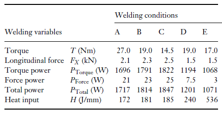
Table 2 – Measured and calculated welding variables
The torque T applied by the rotating tool and the longitudinal force FX have been recorded during welding. In all cases, both variables increase sharply during the
plunge and dwell phases, and then decrease slowly towards a steady state reached during the advancing phase. The measured torque was stable during welding of the joint central part (where the specimens were cut), suggesting that the welding conditions were uniform for all specimens taken from a given welded joint. The steady state values for each welding condition are shown in Table 2. The mechanical power (PTotal) used to achieve welding is calculated as the sum of the torque and longitudinal force contributions:
PTotal = PTorque + PForce = Tω + FX v
and the heat input H as
H = PTotal/v
The calculated values of PTorque, PForce, PTotal and H are also shown in Table 2 for each welding condition. First, the longitudinal force contribution to the total power is almost negligible with respect to the torque contribution as its proportion remains below 1.5% in all cases. The results also show that the heat input is not strictly correlated to the welding pitch. For example, the heat input is almost identical for cases B and C while the welding pitch decreases from 0.67 to 0.5. Moreover, cases C and D have the same welding pitch (k = 0.5), but the heat input is 30% higher for welding condition D. This suggests that the advancing speed (see welding conditions A vs. D) has a larger effect on the heat input as compared to the rotational speed (see welding conditions A vs. C). Earlier work from the authors10 has shown that the contact condition at the tool interface with the welded plates is not constant for different values of the rotational speed, as the friction between the material and the tool increases when the rotational speed decreases. As a result, the torque power does not vary in direct proportions with the rotational speed because the deformed volume is larger and the plastic strain power is greater for low rotational speeds. Therefore, it can be expected that for a given welding pitch, the heat input will be higher for welds produced with a lower rotational speed.
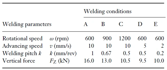
Table 1 – Welding parameters for the five welding conditions
Access the Full Scientific Paper
You have read an excerpt of this scientific paper on Friction Stir Welding. To gain full access to the complete document in PDF format, please fill out the form below.
Section snippets
3 – Microstructural characterization
4 – Mechanical characterization
5 – Failure analysis
6 – Discussion
7 – Conclusion
The effects of the advancing speed and the rotational speed on the microstructure and the mechanical properties of friction stir welded AA 7075-T6 sheets were studied. The fatigue strengths of sound joints made in five velocity conditions were measured and the results were compared to tensile testing results. The relationship between the welding pitch and the fatigue strength of FSW joints was analyzed using micrographs, microhardness
maps and fractographic observations.
The fatigue strength of FSW joints is determined by a competition between two failure mechanisms that are related to the welding pitch. First, fatigue cracks can initiate at the root of circular grooves left at the weld surface by the tool. These circular grooves are the most detrimental failure mechanism for a high welding pitch as their size increases with increasing pitch. The average fatigue joint efficiency is the lowest (less than 60%) when this mechanical weakness is responsible for the failure.
The second mechanism is crack initiation at locations where the base material or the weld is weakened by the heat input. The important material softening in the HAZ and/or the presence of sub-surface defects caused by excessive material stirring become the weakest link in the welded joint for a low welding pitch. When the fatigue strength is controlled by thismetallurgical weakness only, the highest fatigue joint efficiency is obtained (82% at low stress amplitude).
The presence of lateral lips at the edges of the weld surface is also detrimental to fatigue strength. These lips, observed for an intermediate welding pitch, can significantly decrease the fatigue strength, as an average joint efficiency of 66% is measured in this case. It can be expected that lip free joints would exhibit better fatigue strength. A better knowledge of the lip formation mechanism in relation with process parameters would be helpful to optimize the FSW process.
Acknowledgments
The authors wish to acknowledge the National Science and Engineering Research Council (NSERC), the National Research Council of Canada (NRC) and the REGAL research center for their financial support.
