
Relationship between FSW parameters, hardness and tensile properties of 7075-T6 and 2098-T851 similar butt welds
L. Dubourg, R. Amargier, M. Jahazi
Aerospace Manufacturing Technology Centre
Institute for Aerospace Research
National Research Council Canada
5145 avenue Decelles, Montréal, Québec, Canada, H3S 2S4
Abstract
The present study investigates the effects of FSW parameters on mechanical properties of heat treatable aerospace aluminium alloys. Specifically, how the welding and rotational speeds of the FSW tool impact the hardness and the yield strength of welds. Butt configuration, 2-mm sheets of AA7075-T6 and, in another hand, 3,2-mm sheets of AA2098-T851 were assembled in butt joint configuration. FSW was carried out by using a cylindrical threaded pin and by varying welding and rotational speeds. Welded samples were characterized by optical microscopy, microhardness and tensile testing. Results of the two weld configurations are merged in order to determine the relationship between FSW parameters, hardness and tensile properties.
The study highlights:
i)
Two typical hardness profiles for welds performed at low or high welding speed respectively. At low speed, i.e. lower than 1000 mm/min for 7075 and 900 mm/min for 2098, the weld is characterized by a low and stable hardness in the Weld Nugget (WN), a wide Heat Affected Zone (HAZ) and a significant drop in hardness in the HAZ compared to the WN. By contrast, a weld performed at high welding speed shows a narrow HAZ, a high WN hardness and no significant drop in hardness in the HAZ.
ii)
Clear linear correlations can be established between the welding speed, the WN hardness, the overall joint width and the drop in hardness into a weld. For example, overall joint width decreases when the welding speed increases in 7075 and 2098 welds. A similar trend is observed between the welding speed and the yield strength, the yield strength increasing when the welding speed increases.
iii)
No significant effect of the rotational speed on the hardness values and the yield strength was observed. It appears that mechanical properties are more sensitive to welding speed than to rotational speed in the case of precipitation hardening 7075-T6 and 2098-T851 alloys. The heat input, via the welding speed, may be the key factor of the relationship between FSW parameters, hardness and yield strength.
iv)
By abstraction of the grain refinement in WN, the observed hardness increase in the welds may be explained as follows. At the beginning of the process, WN and HAZ are exposed to high temperatures for a certain time, which results in the coarsening of the hardening precipitates and in the hottest zones (i.e. the WN and TMAZ) to their dissolution. This causes an overall hardness decrease in these two zones. After welding, natural ageing occurs resulting in hardness increase. This phenomenon has been highlighted by heat treatments of 2098-O in the interval 350 – 500°C that indicated significant precipitate dissolution, a high natural ageing response and thus a hardness increase. For example, heat treatment at 500°C caused a hardness increase of 30 HV after a natural ageing of one week. By contrast, low temperatures heat treatments in the range 100 to 350°C resulted in a low dissolution and no-natural ageing effect.
v)
The 2-step hardening phenomenon may explain the two typical hardness profiles resulting from low and high welding speeds and the observed interdependence between the welding speed and the hardness values. At low welding speeds, the heat input is high, leading to a wide HAZ, a high precipitate dissolution rate in WN and thus a significant hardness increase in WN due to natural ageing. The combination of these 2 phenomena explains the drop in hardness in HAZ just outside the WN hardness plateau, i.e. where the temperature is high enough for a significant precipitate coarsening but not high enough for precipitate dissolution. By opposition, at high welding speeds, the heat input is lower, thus a narrower HAZ is produced , a limited coarsening occurs in WN, leading to higher hardness values, and the absence of drop in hardness in WN due to low natural ageing.
vi)
This drop in hardness located in HAZ may be the key factor of the 7075 and 2098 FSWed tensile strength. In fact, welds with the highest hardness in this zone show the highest yield strengths and a correlation may be shown between these 2 factors. This confirms the predominant role of the welding speed on the yield strength.
1 – Introduction
Studies conducted on FSW of aluminium show that numerous process parameters can affect the weld properties. The tool shape [1-4] welding speed [5-9], rotational speed [5-8, 10], feed rate [6, 9, 11], welding forces [12, 13] and position of the pin axis [11, 14] may affect the joint size, microstructure, welding temperature, hardness and ultimate tensile strength (UTS). The present work investigates the effects of welding and rotational speeds on the hardness and the tensile properties of welds. Two heat treatable aerospace aluminium alloys namely 2-mm sheets of AA7075-T6 and 3.2-mm sheets of AA2098-T851 were assembled in butt joint configuration. Finally, a relationship between these FSW parameters, the hardness and the yield strength is proposed.
2 – Experimental set up
FSW trials were performed on a MTS I-STIR machine using the position control welding mode. Two different weldments were produced with standard FSW tools made of H13 tool steel. In both cases, the tool shape consisted of a cylindrical threaded probe and a smooth concave shoulder. A probe diameter of 3 mm and a diameter shoulder of 10 mm were used for the welding of 2-mm thick AA7075-T6 plates. A similar tool with a probe diameter of 6.3 mm and a shoulder diameter of 12.7 mm was used for the welding of 3.2-mm thick AA2098-T851 plates. The weld axis was perpendicular to the rolling direction of the parent plate. 300 x 150 mm2 plates before welding were joined in the butt configuration. The influence of welding speed (transverse speed V, ranging from 30 to 1200 mm.min-1) and rotational speed (ω, ranging from 600 to 1800 RPM) was investigated. The weld quality was controlled by metallurgical analysis. Fig. 1 shows a cross section of the weld.
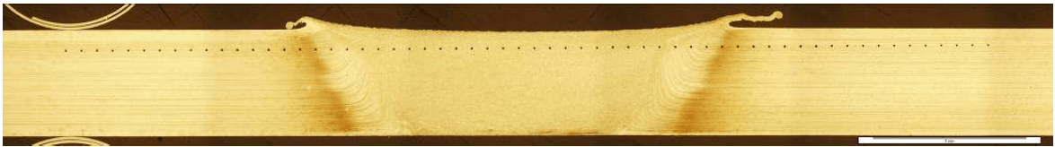
Figure 1: cross section of AA2098-T851 weld, 3,2-mm tick
In order to evaluate the weld quality and to perform the microhardness measurements, the cross section of the welds was polished to a mirror finish (diamond paste with a grain size of 0,5 μm) and etched with Keller’s reagent. Hardness mapping was conducted through the weld cross section over a length of 30 mm with a sampling step of 300 μm and a load of 300 g applied for 15s. Fig. 2 shows two typical hardness profiles of 7075- T6 welds. The red dot profile was measured on a weld performed with a high heat input, i.e. a low welding speed (200 mm/min) and a high rotational speed (1550 RPM). The blue dot profile was measured on a weld carried out with a low heat input weld, i.e. a high welding speed (1100 mm/min) and a low rotational speed (850 RPM). The following observations can be made:
• The hardness in WN is stable. For the low heat input mode, the hardness in WN is slightly higher than for the high heat input mode.
• In the high heat input weld, a significant hardness drop in the HAZ compared to the WN is observed. By contrast, no significant drop in hardness is observed in the high heat input welds
• The overall joint width is wider in the weld performed at high heat input than at the low energy input.
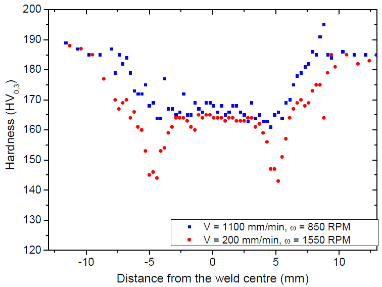
Figure 2: General hardness trends in AA7075-T6 welds. Red dots: high heat input welding, welding speed of 200 mm/min and rotational speed of 1550 RPM. Blue squares: low heat input welding, welding speed of 1100 mm/min and rotational speed of 850 RPM
As shown in Fig. 3, similar hardness trends are observed in AA2098-T851 welds: a plateau in WN, a drop in hardness in HAZ and a widening of HAZ with the heat input increase. Based on the above observations, three evaluation criterions were defined: the WN hardness, the minimum hardness (HVmin) and the HAZ width, as shown in Fig. 4. The WN hardness corresponds to the hardness plateau located in WN. The minimum hardness of the entire weld is always located just out of TMAZ, as shown in Fig. 4. The overall joint width is measured from the minimum hardness threshold of the base metal: 180 HV in AA7075-T6 and 163 HV in AA2098-T851.
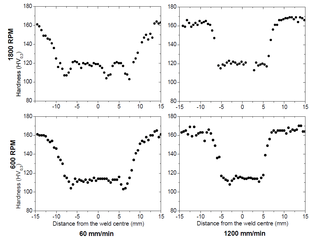
Figure 3: Overview of representative hardness profiles in AA2098-T851 weld cross section according to the welding speed and the rotational speed.
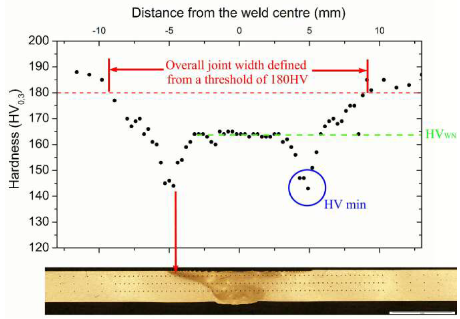
Figure 4: Standard hardness profile and evaluation criterion definition used for the sample characterization. AA7075-T6 weld, 2-mm thick, welding speed of 200 mm/min, rotational speed of 1550 RPM.
Three specimens for tensile testing were machined out from the central part of each welded panel according to the ASTM E8M-01 standard. Cross sections of 12,7-mm width and 60-mm gauge length were used for all-welded samples. The length of the specimens is parallel to the rolling direction of the as-received material, which is normal to the weld length. Yield stress (Ys) is measured from each specimen and afterwards an average on the 3 measured values after correction is calculated. Any sample having a major defect, such as wormhole, kissing-bond or lack-of-penetration, has been selected for the tensile tests.
3 – Results
3.1 Welding of AA7075-T6
Figures 5.a and 5.b show the effects of the welding speed (V) and rotational speed (ω) on the minimum hardness (HVmin). It is clear that a strong correlation exists between the welding speed and the minimum hardness. A similar trend was observed in FSWeds of AA2024-T3 [15]. An increase of the welding speed causes an increase of the minimum hardness as shown in Fig. 5.a. Since a higher welding speed results in a lower energy input and lower process temperatures, the mechanical properties of the heat treated AA7075 material are probably little altered. Therefore, the drop in hardness is reduced. However, a steady state appears for welding speeds higher than 1000 mm/min. Interestingly, the rotational speed does not seem to impacting the minimum hardness (see Fig. 5.b).
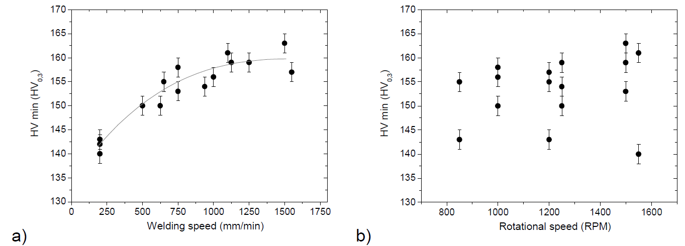
Figure 5: Minimum hardness in AA7075-T6 welds as function of: a) welding speed, b) rotational speed.
The WN hardness shows a certain linear correlation with the welding speed as shown in Fig. 6.a. The plateau hardness increases in a small range from 163 HV to 174 HV for welding speeds from 200 to 1500 mm/min. Besides, the trend is not as clear as for the (HVmin) one and the uncertainty is higher because the plateau is not clearly observed in all samples. Again, no significant effect of the rotational speed on the hardness values is observed.
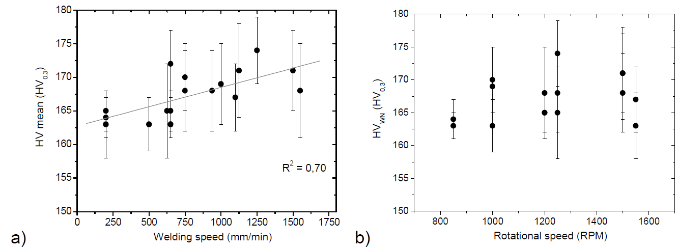
Figure 6: WN hardness in AA7075-T6 welds as function of: a) welding speed, b) rotational speed.
Fig. 7 shows the evolution of the overall joint width with welding parameters. The overall joint size shows a strong linear relationship with the welding speed, it decreases with increasing welding speed. The overall joint width ranges from 23 mm to 14 mm for welding speeds from 200 to 1500 mm/min This is consistent since less energy is generated by increasing the welding speed. Therefore the base metal is altered in a narrower band. By contrast, no clear relationship appears with regards to the rotational speed, as shown in Fig. 7.b suggesting that the energy input does not significantly depend on the rotational speed.
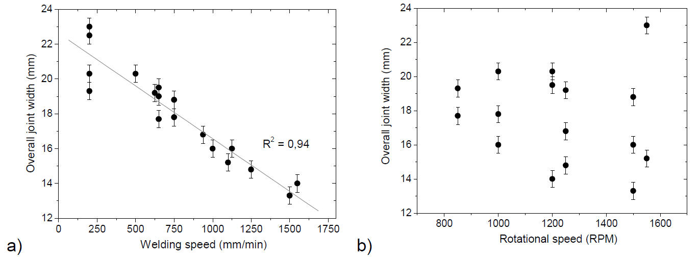
Figure 7: overall joint width in AA7075-T6 welds as function of: a) welding speed, b) rotational speed.
The higher yield strength (average of 424 MPa on 3 samples) was obtained with a welding speed of 2000 mm/min (see Fig. 8.a). This value corresponds to a joint efficiency of 84% in terms of tensile yield strength. As mentioned previously, the welds having a metallurgical defect are rejected from this analysis. The direct impact of the welding speed on the yield strength of 7075-T6 welds may be confirmed by Fig. 8.a. The yield strength and the welding speed follow a linear relationship. This behaviour may be explained by the following phenomena. As shown in Fig. 5.a, an increase of the welding speed results in an increase of the minimum hardness. Therefore, an increase of the minimum hardness results in an increase of the yield strength, the minimum hardness zone being the weaker point of the weld. This hypothesis may be validated by the failure location of the tensile coupons. The great majority of coupons are fractured in the TMAZ/HAZ zone which is the location of the minimum hardness too. Consequently, a high welding speed results in high yield strength. Once again, based on the hardness measurements, the rotational speed does not show any specific impact on the yield strength as shown in Fig. 8.b.
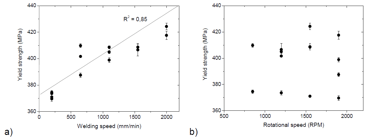
Figure 8: a) Yield strength as function of welding speed for 7075-T6 welding, Yield strength as function of rotational for 7075-T6 welding
Zugriff auf das vollständige wissenschaftliche Papier
Sie haben einen Auszug aus diesem wissenschaftlichen Dokument über das Rührreibschweißen gelesen. Um Zugang zum vollständigen Dokument im PDF-Format zu erhalten, füllen Sie bitte das unten stehende Formular aus.
Section snippets
3.2 Welding of AA2098-T851
The results reported in Figure 9 for the AA2098-T851alloy show mostly the same trends observed in the previous analysis for the 7075-T6 welds. The minimum hardness (HVmin) increases and the overall joint width…
4 – Discussion
Clear linear correlations may be established between the welding speed, the WN-TMAZ hardness, the overall joint width and the minimum hardness. By abstraction of the grain refinement in WN, these behaviours may be explained by the 2-step model of hardness prediction in FSWed heat treatable aluminium alloys proposed previously [16-18]. In a first step, the hardening precipitates present in 7075-T6 and 2098-T851 are coarsened due to the heat flow generated by the FSW tool. In the hottest zones (i.e. WN and TMAZ), the precipitates…
Conclusions
Correlations may be highlighted between the welding speed, the WN hardness, the overall joint width, the drop in hardness and the yield strength. At low speed, the weld is characterized by a low and stable hardness in WN, a wide joint, significant drop in hardness in the HAZ and lower yield strength. By contrast, a weld performed at high welding speed shows…
Acknowlegments
The authors thank Maxime Guérin for FSW experiments, Eric Poirier for the chemical etching of samples, Emmanuel Garrec and Marius Banu for tensile testing.