
Non-destructive detection of lack of penetration defects in friction stir welds
C. Mandache, D. Levesque, L. Dubourg and P. Gougeon
National Research Council Canada, Ottawa, ON, Canada
Institut Maupertuis, Campus de Ker Lann, Bruz, France
This study focuses on the comparative investigation of different non-destructive inspection (NDI) techniques for detecting the lack of penetration discontinuities in butt joint friction stir (FS) welds. A variably sized lack of penetration has been introduced purposely by progressively changing the tool pin’s length. While inspecting the weld from the discontinuity side provides results of higher sensitivity, service inspection of the FS welded components requires evaluation of the welding tool’s side, opposite the defect containing one. Non-destructive techniques amenable for inspection from either the tool side or the far side of the weld are analysed, and results from inspection are presented for comparison. Subsequently, bending tests and metallographic examinations were employed to confirm the side of the lack of penetration defects and correlate these results with the NDI capabilities.
Key-words: Non-destructive evaluation, Friction stir welding, Lack of penetration, Eddy current, Ultrasonic waves, Inspection
1 – Introduction
Friction Stir (FS) welding uses a tool to generate heat by friction and stir the parent materials; in the process, the heat does not melt, it only plasticises the materials1. Friction stir welding is gaining acceptance in the manufacturing of components and structures for transport industries, such as aerospace, automotive, naval and railway1. Lower cost, repeatable and fast manufacture, increased strength, good surface finish and environment friendliness (no fumes) are the specific characteristics that contribute to the attractiveness of FS welding to the aerospace industry. Aluminium alloys in the 2xxx and 7xxx series are selected for aerospace applications owing to their high strength and low weight, and FS welding has the potential to replace most of the fastened structures made from these alloys. Unlike fusion welding, FS welding results in components of strength close or similar to the parent materials. On the other hand, since the metal does not melt and no filler material is added, the types of defets found in FS welds are different from those in fusion welding. This aspect raises new challenges for the non-destructive inspection (NDI) technicians who will need to adapt their inspection procedures and the interpretation of the data from other types of conventional weld inspections. Moreover, reliable non-destructive evaluation plays an important role in the acceptance and expansion of this joining technology in the industry.
The FS welding process parameters are greatly affecting the quality of the weld; therefore, the tool design, the welding tool forces, as well as the torque, angle, and position of the pin axis, and the tool’s linear and rotational speeds need to be carefully selected2,3. They influence a series of interconnected properties, such as the weld’s microstructure, hardness, tensile strength, residual stresses and electric conductivity1-4. The welding pin exerts in-plane (horizontal) and downward (vertical) forces. Controlling the downward force is important in establishing the weld’s penetration depth. However, through an inaquedate choice of welding parameters, tool wear and part deformation during welding could inadvertently create lack of penetration discontinuities in FS welds. This type of defect is an important drawback to the acceptance of FS welding in the industry because the root flaws are seen as crack initiation sites and because they have a significant influence on the fatigue behaviour of the welded part5-6. For instance, it was found that the fatigue life of a 4 mm thick AA 2024-T3 butt welded specimen containing lack of penetration defects was 33-80 times shorter than that of a flaw free weld6.
In this work, various non-destructive evaluation techniques are employed to establish the effect of the pin’s length and their capabilities to detect the existence of lack of penetration discontinuities. In fusion welding, this type of flaw is due to inadequate joint penetration at the rool of the weld. Although it represents a common type of defect in many different welding processes, it has a higher prevalence in FS welding due to the improper welding tool down force or tool wear-out. The results of the NDIs are then correlated with destructive examinations, such as metallographic observations of the cross-section of the weld, defect size and orientation. Bending tests are also performed in order to confirm the criticality of the certain size lack of penetration defects.
1 – Specimen and inspection techniques
The force exerted on the weldingtool faciliates good pin penetration but does not allow the pin to be in contact with the backing surface because this could damage the tool and welding setup. In general, the pin to back distance is always >0, but this could induce lack of penetration defects, as schematically shown in Fig. 1. These types of flaws are very common in butt joints.
The present study uses fives NDI techniques:
(i) phased array ultrasonic waves
(ii) laser generated ultrasonic waves with synthetic aperture focusing technique (SAFT) processing
(iii) conventional eddy current
(iv) pulsed eddy current
(v) liquid penetrant testing.
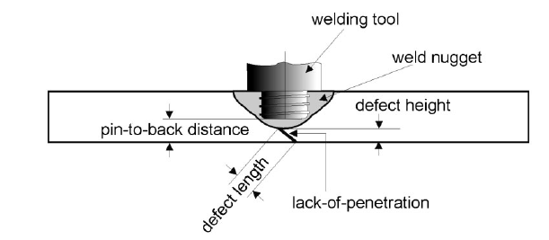
Figure 1: Schematic representation of butt weld including descriptive terminology used in this paper
They are all used to detect a lack of penetration defect of varying sizes introduced in an Al 2024 butt weld using a controllable pin penetration. All these techniques have their own advantages and disadvantages; the focus of this work is not to quantitatively compare them but to analyse their capabilities in terms of sensitivity to the defect’s geometry characteristics. It is important to note that the liquid penetrant and conventional eddy current techniques are applied from the side of the specimen with defect, while the other techniques are applied form the opposite side (the welding tool size) of the butt weld.
The butt weld analysed in the study was produced with an MTS FSW I-STIR equipment. The total welding distance, from pin entry to pin exit, was 345 mm. Coupons (400 x 200 mm) of AA 2024-T3 were machined from 2-56 mm thick plate material, and butt welds were produced with a welding tool made of H13 steel. The rolling direction of the plates was placed parallel to the welding path. The tool consisted of a cylindrical threaded retractable pin having a diameter of 6-3 mm and a smooth concave shoulder with a diameter of 19-0 mm. Plates of similar dimensions were placed on a steel backing anvil and clamped along the two long edges. The welding parameters consisted of a rotational speed of 1000 rev min-1, a travelling speed of 10 mm s-1 and a tilt angle of 2°. The tool (i.e. pin and shoulder) penetration increases linearly from 1-2 mm at the beginning of the weld to 2-5 mm at the end of the weld, as schematically illustrated in Fig. 2a. The tool uses a retractable pin, whose length varies linearly from the beginning to the end of the weld, while keeping the shoulder penetration constant, at 0-2 mm. This introduces a variable weld depth and, consequently, a decreasing depth lack of penetration discontinuity. A picture of the butt weld specimen after machining is shown in Fig. 2b. Finally, the tool side of the specimen is mechanically machined (0-2 mm taken off) to remove any surface asperities resulting from the welding that could influence the NDI results. Figure 2c schematically shows the pin and shoulder penetration into the plate. It is important to note that the weld depth is larger than the pool penetration, according to previous observations7. This aspect will be discussed further in the “Destructive testing” section of this paper.
Based on the discussion above, the tool penetation in the investigated specimen, after machining, can be described by the following linear equation, where x is the position along the weld, and x=0 represents the weld start.
Tool_penetration (mm)=(1-3/345)x+1-0(1)
Naturally, after machining, the maximum value of the defect height (as defined in Fig.1) for the lack of penetration, at any location along the weld, is the coupon thickness, i.e. 2-36 mm, minus the tool penetration. However, in practice, the vertical dimension is much less than this theoretical estimation, as will be discussed in the “Destructive testing” section.
2 – Non-destructive inspection
Using the butt joint FS welded coupon described in the previous section, the results obtained with five different NDI techniques are presented here. Liquid penetrant and conventional eddy current techniques were used to inspect the weld from the far side, i.e. the side that contains the lack of penetration defect, while the three other techniques (pulsed eddu current, phased array ultrasonic waves testing and laser generated ultrasonic waves with SAFT) were used to inspect the weld from the welding tool side, i.e. the opposite side with respect to the lack of penetration defect. In that follows, only summary descriptions of the underlying principles of the non-destructive testing techniques and data processing algorithms are given. Detailed information regarding the NDI techniques can be found in the references provided.
2.1 Ultrasonic testing
Ultrasonic waves propagating in a specimen under test provide great information about its non-visible structure based on the transmitted and/or reflected signals. Ultrasonic waves are commonly used in the inspection of welds; however, for the present case, there are some additional complexities associated to the small thickness of the specimen, leading to difficulties in focusing the ultrasonic beam on the area interest.
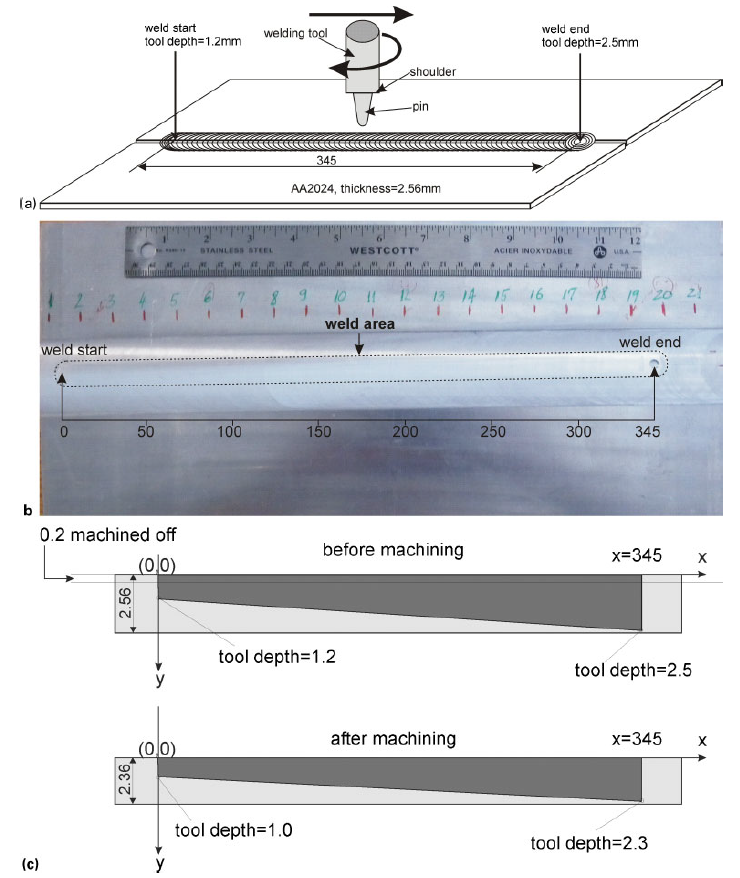
Figure 2: a schematic drawing and dimensions of butt weld, b picture of specimen from tool side after removal of weld asperities (0-2 mm of thickness) and c schematic (not to scale) of tool penetration depth before and after surface machining of weld: all dimensions are given in mm
Phased array ultrasonic waves
Phased array ultrasonic wave testing has gained NDI acceptance in the last few years, and it is now customarily employed in weld inspection applications. Its advantages over conventional ultrasonic inspections come from the use of multiple wave generating elements and the ability to focus and stir the ultrasonic beam without movement of the probe, while the images are formed by constructive interference.8,9 On the testpiece under study, the phased array ultrasonic testing was performed at discrete locations, at intervals of 19mm along the weld, in order to capture information regarding the lack of penetration discontinuity. The inspections were performed from the tool side (opposite to the discontinuity side) using a linear array of 16 elements, creating waves of 10 MHZ frequency, adapted with a shear wave wedge able to generate waves at 60° incidence in steel. The wedge and array assembly were able to generate a beam spread between 45 and 70° in the specimen under test. The probe was positioned away from the weld location and oriented in such a way that the emerging ultrasonic beam is perpendicular to the weld legth axis. Selected results are shown in Fig. 3 as sectorial scan presentations. The lack of penetration indications are seen between the vertical cursors, corresponding to a range of sound path length from 5-94 to 6-83 mm from the probe, as theoretically predetermined based on the wave propagation principles. The colour intensity is proportional to the reflected signal amplitude and, consequently, to the lack of penetration size. Based on the discrete inspections presented, the phased array ultrasonic wave technique could detect reflections from the discontinuity up to positions of >160 mm but <179 mm from the start of the weld. Although indications between the cursors at 217 and 235 mm could be seen in the following results, these do not exceed the background noise level of the signal; therefore, they could not be reliably attributed to the presence of discontinuities in the weld.
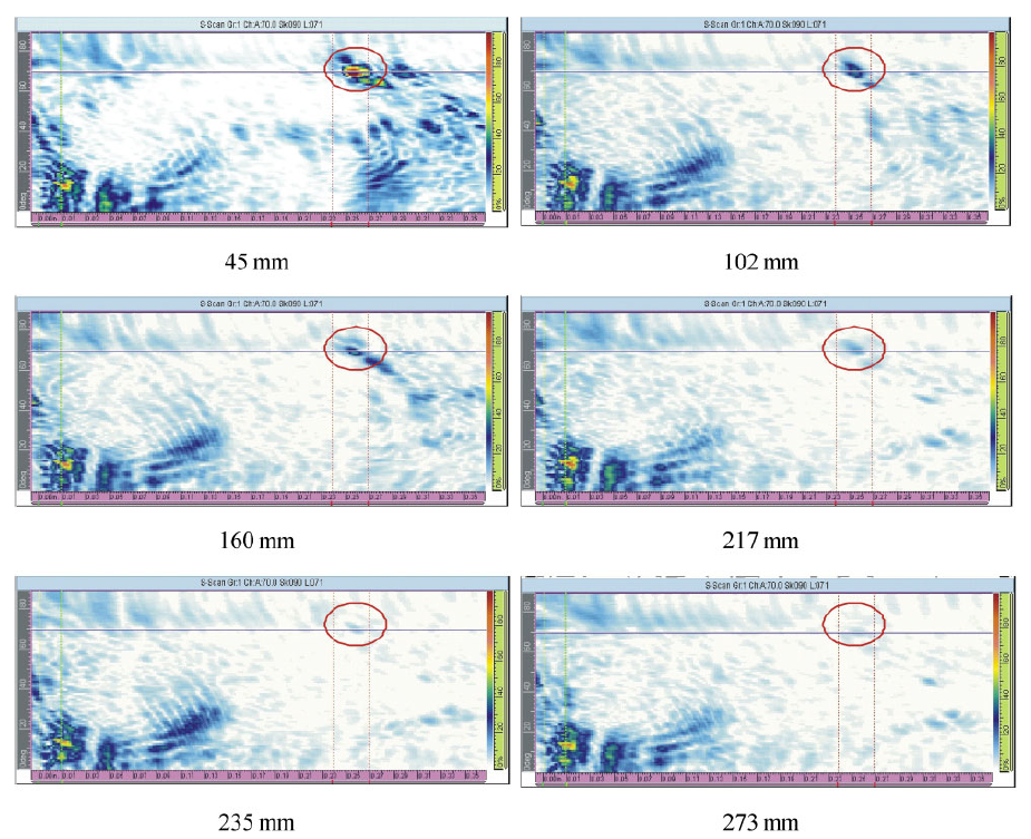
Figure 3: Phased array ultrasonic sectorial scans at various locations along butt weld (distances from beginning of weld)
Synthetic aperture focusing technique
The SAFT algorithm uses Fourier time domain information and allows synchronization of the ultrasonic signals scattered back in different directions from each point in the weld region. For these scans, the spatial sampling step was selected to be 0-1 mm for both x and y directions. The technique used laser generated ultrasonic waves with a spot size of ~ 50 µm from a 35 ps duration Nd/YAG laser in its third harmonic. The detection used a long pulse Nd/YAG laser, and demodulation was performed with a photorefractive interferometer; frequenties of up to 220 MHz were successfully used in this inspection. The images shown in Fig. 4 represent the SAFT processed laser ultrasonic inspections corresponding to six different pin locations along the weld. The scans are individual areas of 10×10 mm, and surface machining of the part is visible as lines from the bottom left corner to the top right corner. Clear indications of lack of penetration are visible in the scans closer to the weld start. Towards the middle of the weld, as in the scan after 164 mm, an interrupted lack of penetration indication could be seen; however, for a coordinate along the length of the weld of >245 mm, no lack of penetration is observed, and the weld is considered free of these types of discontinuities. According to equation (1), at a coordinate equal to 245 mm, the tool penetration depth is 1-92 mm in the 2-36 mm total thickness specimen.
Zum vollständigen wissenschaftlichen Artikel
Sie haben gerade einen Auszug aus diesem wissenschaftlichen Dokument zum Thema Rührreibschweißen gelesen. Um auf das gesamte Dokument im PDF-Format zuzugreifen, füllen Sie bitte das untenstehende Formular aus.
Section snippets
2 – Non-destructive inspection
2.2 Eddy current testing
2.3. Liquid penetrant testing
3 – Destructive testing
Metallographic examinations performed at 13 locations along the length of the weld revealed the presence of lack of penetration defects until ~ 150 mm from the weld start. However, besides lack of penetration, another type of defect is present, consisting of a thin layer of oxide, customarily called “kissing bond“1. Kissing bonds are known to be present at the intimate contact of two adjacent surfaces but without actual metallurgical bond of cohesion forcs. The types of defects propagate from the…
4 – Summary and discussions
According to the destructive testing and metallographic examinations, the lack of penetration is confirmed up to 149 mm from the weld start, while at 176 mm, the lack of penetration is no longer observed, while kissing bonds are present up to a coordinate of 257 mm. Conventional eddy current and liquid penetrant techniques…
Conclusions
This study investigated the capabilities of five different non-destructive testing techniques in inspecting lack of penetration discontinuities in butt joint FS welds. A specimen with a varying lack of penetration, introduced by adapting the welding tool penetration, was specially manufactured for this purpose. Two of the five inspection techniques, i.e. conventional eddy current and liquid penetrant, were used to investigate the weld from the side with lack of penetration. The other three techniques, i.e. phased array ultrasonic waves, laser generated ultrasonic waves with SAFT processing…
Acknowlegments
The authors would like to thank M. Brothers from the Institute for Aerospace Research as well as M. Patry, M. Lord and F. Nadeau from the Industrial Materials Institute of the National Research Council Canada for their contributions to this project.