


Experimental Methodology to Identify Optimal Friction Stir
Welding Parameters Based on Temperature Measurement
Moura Abboud1,2,*, Laurent Dubourg2, Guillaume Racineux3 and Olivier Kerbrat1
1 Department of Mechatronics, University of Rennes, ENS Rennes, CNRS, IPR, UMR 6251, 35000 Rennes, France; olivier.kerbrat@ens-rennes.fr
2 STIRWELD, 35000 Rennes, France; laurent.dubourg@stirweld.com
3 Central School of Nantes, Research Institute in Civil and Mechanical Engineering, 44321 Nantes, France; guillaume.racineux@ec-nantes.fr
* Correspondence: moura.abboud@ens-rennes.fr
Abstract: Friction stir welding (FSW) is a widely employed welding process, in which advancing and rotational speeds consitute critical parameters shaping the welding outcome and affecting the temperature evolution. This work develops an experimental methodology to identify optimal FSW parameters based on real-time temperature measurement via a thermocouple integrated within the tool. Different rotational and welding speeds were tested on AA5083-H111 and AA6082-T6.
Our results underscore the importance of attaining a minimum temperature threshold, specifically 0.65 times the solidus temperature, to ensure high-quality welds are reached. The latter are defined by combining temperature measurements with joint quality information obtained from cross-sectional views. Our research contributes to advancing the efficiency and effectiveness of friction stir welding in industrial settings. Furthermore, our findings suggest broad implications for the manufacturing industry, offering practical insights for enhancing weld quality and process optimization.
Key-words: thermocouple; rotational speed; advancing speed; quality; FSW operating window; heat generation
1 – Introduction
Friction stir welding (FSW) is a solid-state welding method invented by The Welding Institute (TWI) in 1991, allowing for the assembly of two workpieces, using a rotational rigid tool (Figure 1) [1]. It has emerged as a pivotal technique employed in mass production, a significant milestone within the industrial sector. Its welding speed and exceptional versatility, especially with lightweight materials, have propelled it to the forefront of industrial applications. This technique enables one to control melting defects [2] and obtain high mechanical properties of the weld [3,4]. Another remarkable advantage of the process is its ability to operate below the melting point of the workpiece material, making it possible to weld aluminum alloys that cannot normally be joined by conventional fusion welding techniques [2,5]. Therefore, understanding heat generation phenomena is crucial towards achieving successful welds and optimizing the welding process, given that industrials are interested in reaching the highest welding speeds [6]. This phenomenon is the result of (i) the plastic deformation of the material around the tool, depending on advancing and rotational speeds; and (ii) the friction between the tool and the material, governed by the shape of the rotating tool [6–8].
However, weld quality control is a challenging task due to temperature variation throughout the weld [8]. In other words, temperature has an important influence on the porosity rate [9], which could dramatically decrease the mechanical properties of the welded part [10,11]. Moreover, for aluminum alloy strengthened by second phases, the welding temperature will affect the dissolution, coarsening, or precipitation of second phases. That could result in a significant decline in the alloy’s mechanical properties as reported in the literature [12]. Accordingly, ISO-252395 [13] specifies the requirements for determining the capability of a manufacturer in order to use the friction stir welding (FSW) process to reach the specified quality in the final product. One of its primary criteria for assessing the quality of a weld revolves around the presence of porosity defects, which
are categorized into two main types: (i) “hot weld” and (ii) “cold weld” (Figure 2). Hot welds exhibit porosities that form along the top of the weld, creating a groove structure. In contrast, cold welds display porosities located at the bottom of the weld, typically attributed to insufficient penetration forming a tunnel-shape [14].
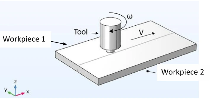
Figure 1 – Schematic of the FSW proccess, with ω as rotational speed and V as welding speed.
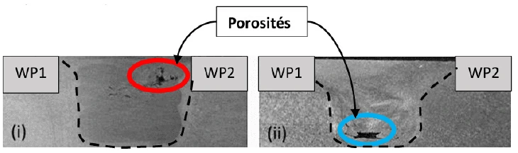
Figure 2 – Porosity defects: (i) hot welds; (ii) cold welds, WP1 workpiece 1, and WP2 workpiece 2.
Pushing welding speeds to their upper limits can lead to outcomes such as porosity defects when not meticulously managed. These defects lead to a welding window consisting of three distinct zones (Figure 3; this welding window serves as a representative scheme for an aluminum alloy, and its values depend on the the material’s characteristics). These areas are classified as follows: a high-quality weld, often referred to as a “good weld”; a “hot weld”, characterized by porosities occurring due to excessive heat produced at high rotational speeds; and a “cold weld”, featuring porosities resulting from inadequate penetration (the result of high advancing speeds) [14–16]. The temperature increases along with the increase in rotational speed and the decrease in advancing speed [17].
To establish the welding operating window, conventional methods typically rely on destructive testing, according to ISO-25239 [13] guidelines. Consequently, extensive testing is required by industrials to derive a set of process parameters. However, our aim is to develop a non-destructive method for defining this window. Given the important role of temperature in Friction Stir Welding (FSW), we propose measuring the temperature to determine the welding operating window. This approach presents a non-destructive advantage, especially considering the intimate connection between temperature and the process parameters. Despite the limited availability of data regarding welding operating windows based on temperature and process parameters, our research focuses on this novel avenue for obtaining high-quality welds. To this end, our work involves an extensive experimental campaign involving two widely used aluminum alloys, specifically AA-5083-H111 and AA-6082-T6, to provide valuable insights into optimizing the welding process.
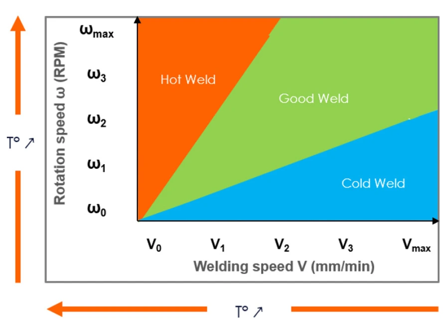
Figure 3 – Representative scheme of FSW operating window zones, and temperature evolution
according to ω and V.
In our study, we begin with a literature review of experimental temperature measurements (Section 2). This is followed by the introduction of a tool-mounted temperature measurement approach and the execution of experiments involving parameter variations while monitoring the temperature (Section 3). Subsequently, the paper discusses the results obtained through porosity analysis and temperature data, along with the establishment of operational windows (Section 4). Finally, the paper concludes with a discussion and offers insights into future directions and conclusions (Section 5).
2 – State of the Art
FSW is a complex process influenced by various parameters. The importance of each parameter can vary based on the specific application and material being welded. In this context, two crucial parameters significantly influence the process: the rotational speed ω and the welding speed V.
Rotational speed holds significant importance as a process parameter. It affects several critical aspects such as the amount of heat generated, the plastic deformation of the material, and the forces applied on the tool, which impact the defect generation and the size of the stirred zone. A low rotational speed can lead to imperfect joints due to insufficient heat input [18] and tends to yield joints with higher hardness [19]. Conversely, a high rotational speed helps stir the material but presents challenges. One challenge is increasing tool wear resulting from intense friction, particularly when dealing with high-strength aluminum, as it will reduce tool life [20]. However, finding the right balance in the choice of rotational speed is crucial, even more so when excessively high rotational speeds may lead to undesirable consequences. Elevated values may lead to an over-aggressive stirring action, potentially inducing flashes and/or porosities within the joint [21]. Simultaneously, if rotational speeds are too low, there may not be sufficient mixing of the mechanical bonding between the welding plates [22]. Therefore, the temperature increases when the rotational speed increases.
The significance of the welding speed in achieving high-quality is equivalent to that of the rotational speed in the FSW process. Extremely high welding speeds can lead to joints with incompletely welded interfaces due to inadequate heat input [23]. This deficiency is particularly notable in cases where the welding speed is excessively high, reducing the thermal cycle duration [24]. Conversely, low welding speeds contribute to increasing the material stirring during the welding process [22]. So, reducing the advancing speed leads to an increase in temperature during FSW.
The interplay between rotational speed and welding speed is extensively documented as a key determinant of weld quality. The optimal combination of these parameters is critical as it dictates the thermal conditions during the welding process regarding whether it leans towards the cold weld (the blue area, Figure 3) or the hot weld (the red area, Figure 3).
To that end, researchers and engineers are interested in determining the optimal parameters, specifically rotational and advancing speeds, for achieving defect-free welded pieces. Numerous experimental temperature measurement methods are employed to define the welding process window. Table 1 outlines the experimental methods employed by researchers over the past 25 years on different aluminum alloys and the temperature limits of a good weld.
These methods (Figure 4) include thermal cameras (IR Camera), the thermoelectric method (TWT), and thermocouples embedded in the workpiece (TC-Workpiece) or the FSW tool (TC-Tool). However, obtaining accurate weld temperature measurements through experimental validation poses challenges.
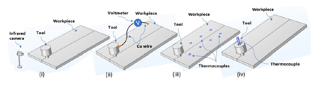
Figure 4 – Experimental temperature measurement methods during FSW: (i) infrared camera, (ii) TWT,
(iii) thermocouples embedded in the workpiece, and (iv) thermocouples embedded in the tool.
In the case of IR cameras [25], issues are related to aluminum emissivity and the measurement of the zones outside the weld, as well as problems with measurement quality if the camera is not well fixed. To validate the accuracy of this method, Ambrosio et al. [8] integrated thermocouples into the back of the workpiece for comparative analysis.
The thermoelectric TWT method [26] is based on the thermoelectric effect where the electric potential generated between the FSW tool material and the aluminum workpiece is associated with the weld temperature. Each tool–workpiece material combination requires a calibration of the voltage temperature relation. Therefore, it involves an extensive study leading to excessive experimental work.
As for the TC-Workpiece [27,28], the significant plastic deformation at the workpiecetool interface poses a primary obstacle. However, interpreting thermocouple measurements becomes intricate due to their extreme sensitivity to location, and caution is warranted in data interpretation. There is a risk of thermocouple destruction by the rotating pin and the intense plastic deformation in the stir zone.
Thermocouples embedded in the FSW tool may experience a time delay if not positioned correctly, as reported by [29].
To conclude, standard temperature measurement methods often lack the repeatability, accuracy, or speed required to obtain a window in an industrial way. Therefore, we recognized the need for further research centered around a straightforward temperature measurement method suitable for industrial use, enabling the determination of the welding window.
Despite their limitations, thermocouples embedded either in the workpiece or in the tool have proven to be the most successful. Therefore, in this study, we utilized a thermocouple embedded in the tool and positioned in the plane of the shoulder as well as in the middle of the tool that measures the temperature of the weld in real time. This choice was driven by the necessity to explore alternative methods for determining optimal parameters that ensure the production of high-quality welds.
Table 1. Experimental temperature measurement methods review. Tm, measured temperature; Tmelt, melting temperature of the material; Ts, solidus temperature; Tmin, minimum temperature of a good weld; Tmax, maximum temperature of a good weld; TC-Tool, thermocouple embedded in the tool; TC-Workpiece, thermocouple embedded in the workpiece; IR, infrared camera; and TWT, tool–workpiece thermocouple.
| Author | Year | Method | Material | Tmin < Tm < Tmax | References |
| D. Ambrosio | 2022 | TC-Tool | AA-6082-T6 AA-5083-H111 AA-7075-T6 | 477 < Tm (°C) < Ts | [8] |
| A. Wright | 2021 | TC-Tool | AA-6111 | Tm = 450 °C | [30] |
| D. Ambrosio | 2020 | TC-Workpiece IR Camera | AA-7075-T6 | Tmin = 350 °C | [21] |
| S. Verma | 2020 | TC-Workpiece | AA-7039 | 283 < Tm (°C) < 390 | [26] |
| T. Wu | 2019 | TC-Tool TC-Workpiece | 2A14-T6 | [31] | |
| G. Sorger | 2018 | TC-Workpiece | HSS | 650 < Tm (°C) < 900 | [32] |
| A. C. F. Silva | 2016 | TC-Workpiece TWT TC-Tool | AA-6082-T6 | Tmax = 500 °C | [27] |
| A. Fehrenbacher | 2013 | TC-Tool-Shoulder TC-Tool-Pin | AA-6061 AA-5083 H111 AA-6061 AA-5083 H111 | 515 < Tm (°C) < Ts 518 < Tm (°C) < Ts 460 < Tm (°C) < Ts 479 < Tm (°C) < Ts | [33] |
| J. De Backer | 2013 | TWT | AA-6082-T6 | Tmax = 432 °C | [34,35] |
| C. Hamilton | 2010 | IR Camera | SSA038-T6 | Tmax = 400 °C | [36] |
| P. Upadhyay | 2010 | TC-Tool | AA-7050 T7451 | Tmax = 350 °C | [37] |
| P. L. Threadgill | 2009 | TC-Workpiece | AA-6061 T6 | Tmax = 500 °C | [38] |
| F. Gratecap | 2008 | TC-Workpiece | AA-2017 T4 | 0.7 Tmelt < Tm (K) < 0.8 Tmelt | [39] |
| Yuh J. Chao | 2003 | TC-Workpiece | AA-2195 | 0.8 Tmelt < Tm (°C) < 0.9 Tmelt | [40] |
| L. E. Murr | 1998 | AA-6061 | Tmax = 425 °C | [41] | |
| M. W. Mahoney | 1998 | TC-Workpiece | AA-7075 T651 | Tmax < Tmelt | [42] |
| W. Tang | 1998 | TC-Tool | AA-6061 T6 | Tmax = 450 °C | [43] |
| C. G. Rhodes | 1997 | TC-Workpiece | AA-7075 T651 | 400 < Tm (°C) < 480 | [44] |
3 – Experimental Approach
A HAAS-VF3 CNC machine with a Stirweld FSW head (maximum rotational speed of 3500 rpm and a critical force of 25 KN) was used to conduct 250 mm welding lines of the aluminum alloy. The selection of 250 mm for friction stir welding lines is based on compliance with ISO-25239 [13]. The specific choice of this length is determined by the standard’s guidelines and requirements for achieving optimal welding results and ensuring the integrity of the welded structures.
Accedi all’articolo scientifico completo
Avete appena letto un estratto di questo documento scientifico sulla saldatura Friction Stir Welding. Per accedere all’intero documento in formato PDF, compilare il modulo sottostante.
Snippets section
4 – Results
The temperature variation is continually monitored through the embedded thermo-couple in the tool, as illustrated in Figure 7 for the AA-6082-T6 material…
5- Discussion
Based on temperature measurements and macrostructural analysis, our objective is to develop a methodology employing temperature data to optimize…
6 – Conclusions
In this study, we presented an experimental methodoloy to identify optimal FSW parameters for AA-6082 T6 and…
