
Limitation of distortion in Friction Stir Welded (FSW) panels using needle peening
S. Larosea, L. Dubourg, C. Perron, M. Jahazi and P. Wanjara
NRC Institute for Aerospace Research, 5145 avenue Decelles, Campus de l’Université de Montréal, Montréal, Quebec, Canada, H3T 2B2
asimon.larose@cnrc-nrc.gc.ca
Friction stir welding (FSWing) induces residual stresses and distortions in welded structures. Such residual stresses reduce the fatigue life of welded components, while the induced distortions prevent the welding of large or thin components. In the present study, needle peening was used to induce additional residual stresses in 2.3-mm thick (FSWed) aluminum alloy (AA) 2024-T3 sheets. This was done with the objective to counterbalance the welding-induced stresses and thus reduce the overall stresses and distortions. The needle peening process, which stems from shot peening, consists of hammering a surface using cylindrical spherical ended shots sliding back and forth in a treatment head. An instrumented needle peening machine was used to carry out peening on as-received (or bare) and bead-on-plate FSWed AA2024-T3 material. In both cases, the width of the peening area corresponded to that of a typical weld. The influence of the peening process parameters such as needle size, applied power and travel speed on the surface quality and magnitude of the induced distortions were evaluated. The results indicate that, by increasing the needle diameter from 1.2 mm to 2.0 mm, the peening-induced deflection on bare sheet material increased by an average value of 27% while the roughness average, Ra, decreased by an average value of 47%. It was also found that a surface finish qualitatively similar to that of conventional shot peening could be obtained by using appropriate needle peening trajectories. Finally, needle peening with an applied power of 10% was sufficient for eliminating 37% of the welding-induced transverse curvature and 82% of the welding-induced longitudinal curvature.
Key-words: friction stir welding, needle peening, residual stresses, distortions
Introduction
FSWing is an emerging manufacturing technology that involves a rotating tool consisting of a pin and a shoulder to generate sufficient heat at the weld interface to plasticize and then mix the material to form a consolidated joint. As FSWing is a solid-state joining process, concerns related to fusion welding of aluminum alloys are minimized, such as porosity in the weld zone, hot cracking and loss of mechanical properties. Recently, work on FSWing of aluminum alloy aircraft structures have found that distortion is an issue [1, 2, 3] that needs to be minimized by means of concurrent mechanical or thermo-mechanical processes. As part of an overall program on the development of FSWing for aerospace applications at the National Research Council Canada’s Institute for Aerospace Research, needle peening has been investigated as a mechanical post-process for reducing the deformation induced distortion of the work-piece. A variant of shot peening, needle peening, originates from needle scaling, a metalworking application in which a set of captive needles moving back and forth at high speed is impelled into contact with specific areas of a component to remove rust, scale, and worn paint from the surface, leaving bare metal. Similar to shot blasting, it was found that needle scaling induces a thin layer of compressive residual stresses.
Based on these observations, needle peening has been developed for post-weld treatment to introduce compressive residual stresses, which have been reported to diminish stress corrosion cracking and improve fatigue life of fillet welded joints [4, 5, 6, 7]. As compared to shot peening, needle peening is of particular interest for FSWed joints as the latter can be integrated with the joining process, thereby minimizing the impact of this secondary post processing stage on the productivity level. In this work, the effect of needle peening on bare AA2024-T3 sheets and on FSW induced distortions in AA2024-T3 material was studied.
Investigation of the needle peening process
Description of Needle Peening Equipment. The experiments were performed using a non-conventional needle peening gun (Fig. 1) based on the Stressonic® process, in which electrical energy is converted into mechanical vibration at ultrasonic frequencies (20 kHz) by means of a piezoelectric transducer. The vibration amplitude increases through a series of acoustic boosters up to the sonotrode that is designed to vibrate homogeneously on the entire surface and repeatedly strike the projectiles. Different types of treatment heads with accompanying projectiles can be coupled with the Stressonic® process for surface treatment. In this work, the surface treatment was performed using cylindrical spherical ended shots (also called needles or “spherils”) made of 100C6 steel, which oscillated back and forth in the treatment head installed at the tip of the gun. The process parameters are (1) characteristics of the treatment head (size of spherils, number of spherils), (2) distance between the top of the treatment head and the treated surface, (3) area to be covered by needle peening, (4) trajectory, (5) travel speed and (6) percentage of maximum power of the electric generator (which is related to the vibration amplitude of the sonotrode).


Figure 1: Needle Peening Equipment: (a) Needle Peening Gun (b) Treatment head with needles or spherils
As the only reported work on ultrasonically activated needle peening is the study conducted by Forgues [8] on the effectiveness of the process for extending the fatigue life of welded steel structures using one set of nominal parameters, process characterization was performed as an initial step in the present study.
Preliminary Study. The first tests consisted of needle peening 150mm x 20mm x 2.3mm bare 2024-T3 aluminum sheet coupons (see Fig. 2) by a manual application. Coupons were placed on a steel backing anvil, clamped along the two long edges (see Fig. 3), then unclamped after needle peening. The tests simultaneously investigated the effect of generator power and the treatment head.
Needle peening was manually applied following a straight trajectory along the centerline of the coupons so as to simulate the post-treatment conditions to be applied on the FSWs. The objective for the needle peening operator was to maintain a constant and relatively slow traveling speed. After each test, the induced deflection of the plate and the average surface roughness, Ra, were measured.
Deflection was measured using an analog dial gauge with the coupons placed on a marble table, while the Ra was measured using a Taylor Hobson Form Talysurf S4C profile measurement system.


Figure 2 – Dimensions of the test coupons
Figure 3 – Al plate clamped on the backing anvil
Fig. 4a shows that the treatment head with the 2.0-mm diameter spherils induced a greater deflection than that with 1.2-mm diameter spherils, for each generator power under consideration.
The difference in deflection varied with the generator power, with an average difference of 27%. It is noteworthy that usually three experimental measurements were performed for each condition for statistical analysis and the error bars in figures correspond to the calculated standard deviation. Fig.4b shows that the treatment head with 2.0-mm diameter spherils induced a significantly lower Ra than that with the 1.2-mm diameter spherils. The difference in the Ra was approximately 47%, with a nearly constant ratio for each generator power. Finally, the induced deflection and Ra increased with generator power for both treatment heads (i.e. 1.2-mm and 2.0-mm diameter spherils).
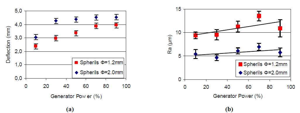
Figure 4 – Effect of spheril diameter and generator power on induced deflection (a) and surface roughness average Ra (b)
Acceda al artículo científico completo
Acaba de leer un extracto de este artículo científico sobre la soldadura por fricción-agitación. Para acceder al documento completo en formato PDF, rellene el siguiente formulario.
Section snippets
Detailed study
Effect of Needle Peening on FSW induced Distorsions
Experimental procedure
Results
Conclusions
This study highlighted the following points. i) Needle peening with large diameter spherils produces larger deflections with lower surface roughness than needle peening with small diameter spherils.
For AA2024-T3 the use of large diameter spherils was observed to provide improved surface finish characteristics. ii) Needle peening with a linear trajectory results in a surface finish markedly different from shot peening. Applying different peening trajectories allowed the identification of an optimal condition that gave an enhanced surface finish, with a good surface recovery by indentations and low surface roughness. The surface finishing that is obtained is qualitatively similar to that obtained by shot peening. iii) Friction stir bead-on-plate welds induce unstable saddle-shaped geometries in rectangular AA2024-T3 coupons. These geometries could be due to plate buckling induced by the welding-induced stresses. Additional investigation would be required to validate this assumption. iv) Needle peening with a low generator power (10%) was found sufficient to remove 37% of the FSW induced transversal distortion and 82% of the longitudinal distortion. In conclusion, this study suggests that needle peening would be a suitable post-process for reducing the FSW induced distortions in AA2024-T3 material.
Acknowlegments
The authors thank S. Benyounes for his technical assistance in conducting the experimental work.