
Design and properties of FSW tools: a literature review
L. Dubourg ᵃ, P. Dacheux ᵇ
ᵃ Aerospace Manufacturing Technology Centre, National Research Council Canada, 5145 avenue Decelles, Montréal, Québec, Canada, H3S 2S4
ᵇ Aluminium Technology Centre, National Research Council Canada, 501, Boul. de l’Université, Saguenay, Québec, Canada, G7H 8C3.
Abstract
For fifteen years, Friction Stir Welding (FSW) has increasingly attracted interest in both industry and academia for welding of aluminium alloys and other low melting temperature metals. The process involves a rotating tool consisting of a pin and a shoulder. The pin is being inserted between adjoining metal pieces. The heat generated by the tool friction brings the metal to a plastic-like state and the pin mixes the pieces together in a sound and homogenous joint. The main advantages of this process, speed, repeatability, no filler and no joint preparation, improved mechanical properties and low residual stress, have made FSW a beneficial method in marine, railway rolling stock, construction and aerospace industries. Applications in aluminium and copper are growing while FSW in titanium and other higher temperature materials are increasingly studied. These progresses are the consequence of the new FSW tool development and a better process understanding. Nevertheless, one of the most important challenges is still the design of the tool shoulder-pin system to assure a good quality weld and to reduce the loads during the process. Consequently, based on an extensive literature survey, a review is presented on FSW tools, covering the design, the properties and the applications. After a brief presentation on the interaction mechanisms between the tool and the metallic sample, the paper describes the typical tool designs and their characteristics. Finally, emerging tool geometries are reported.
1 – Introduction
Friction stir welding (FSW) has quickly evolved since TWI has patented this technology in 1991. The heat generated mainly by the shoulder friction against the base metal brings the metal to a plastic-like state and the pin stirs the adjoining materials together in a sound and homogenous weld. Since melting seems to not be reached, FSW is considered as a solid-state welding process and it can be used in multiple positions and geometries [1, 2]. The main advantages of this process are the relative high welding speed compared with traditional GTAW or GMAW process, the high repeatability, the absence of fumes, shielding gas, filler material, joint preparation and ultraviolet radiation, the high mechanical properties of weldment, low residual stress level and distortion, the ability to weld aluminium alloys which cannot be fusion welded such as 2xxx or 7xxx series and the ability to weld dissimilar materials like Al to steel [1-6].
All these advantages have made the FSW process a beneficial welding method in marine, railway rolling stock, construction and aerospace industries [7]. Moreover, this friction technique can be applied to surface modification for different goals: processing for superplasticity, casting modification, powder processing and metallic matrix nanocomposite elaboration [8]. The advantages of friction surface processing are the relative low amount of heat input, the extensive and controlled plastic flow, the very fine microstructure leading to the superplasticity behaviour of certain alloys (AA7075 [9], AA2024 [10]), the random misorientation of grain boundaries, the mechanical stirring ofthe surface layer and the large forging pressure.
Since the stirring tool is one of the process keys, its development drives the evolution of FSW process. This paper explores the parameters of tool design and their relation to heat generation, material flow and the formation of quality weld. Authors have voluntary limited this review to tools for low temperature and strength materials (aluminium, copper, magnesium, lead). PCBN and W-Re tools used for the welding of high temperature and strength materials (steel, titanium, superalloys) are not reported.
2 – Fundamental principles of Friction Stir Welding
The two phenomena involved in FSW process are the heating by the tool friction on the material and the material flow due to the tool stirring. Experiments and numerical models are intensely used to improve the understanding of these phenomena. However, numerical approach gives access to phenomena difficult to estimate by experiment. Predictive simulations should take into account the following topics: coupled friction/heat generation, plastic flow and slip surface development and finally heat and material flow [5].
2.1. Heat generation
Although FSW energy input is about the same or smaller than arc welding [11], the heat is distributed over a wider zone by the shoulder contrary to a focused arc. Moreover, the intimate contact between the sample and the backing plate acts as a heat sink and dissipates efficiently the heat. Consequently, FSW is considered as a cold welding process leading to low residual stress level and distortion. Heat is mostly generated by the friction between the tool shoulder and the surface of the piece, followed by the high plastic work and the pin friction. Throughout literature, various percentage of the pin contribution to the heating process are available: 2% [1], 20% [1], 25% [12] and 51% [1]. However, a general trend adopts a contribution lower than 5%. The contribution of each component of the process (shoulder friction, pin friction and plastic work) on the heating is clearly underlined by Dong et al. for AA6061 T6 welding [13]. Fig. 1 shows the heat production due to friction alone (Fig. 1.a), plastic work alone (Fig. 1.b) and combinedfriction/plastic work (Fig. 1.c). In the case of friction alone, the temperature under the shoulder (about 350°C) is close to the one under the pin (300°C). However, this temperature is distributed on a larger surface, which causes a higher energy input. Moreover, the heating generated by the pin is close to the surface backing where the heat extraction is maximum. These two phenomena confirm the primary contribution of shoulder friction on the heat generation in the FSW process. In the case of plastic work alone (Fig. 1.b), the global temperature is relatively low (about 100°C under the tool) compared to friction heating (250°C), except under the pin where the strain is higher. This simulation confirms the main role of friction on the heating. Finally, when the two phenomena are combined (Fig. 1.c), the global temperature under the tool is around 250°C with local hotter zones under the shoulder and the pin (>350°C).
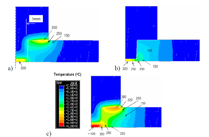
Figure 1: heat generation due to: a) tool friction, b) plastic work, c) tool friction and plastic work. Courtesy of Dong et al. [13].
The heat input by the shoulder friction may be calculated by Eq. 1 [14, 15]. As shown in this equation, the power input increases with the increase of friction coefficient, the forging force (i.e. the normal load acting by the tool), the rotational speed and the shoulder diameter.
q₀ = ⁴⁄₃ π² μ P N R³
Equation 1: q₀: net power (W), μ: friction coefficient between the piece and the tool, P: pressure distribution (MPa), N: rotational speed (rpm), R: surface radius (mm).
The friction in front of the tool generates a plastic-like zone, which is then moved around the tool and deposited on the retreating side. This process is considered continuous along the workpiece. However, if melting occurs in front of the tool due to an excessive heating, less friction is generated due to the slip between the tool and the molten metal. As the temperature decreases, the material returns to a solid state and vice versa. This phenomenon may limit the use of high tool rotations and therefore the use of high welding speeds. Consequently, a material with a low melting point such as AA2024 (solidus temperature of 502ºC) cannot be welded as fast as AA5083 (solidus temperature of 574ºC). This is illustrated in Fig. 2, the AA2024 process window being smaller than the one of AA5083 [1, 16]. The melting point of different aluminium alloys in Fig. 2can be used to sort the size of their process window (solidus temperature: 502ºC for AA2024, 477ºC for AA7075, 574ºC for AA5083 and 582ºC for AA6061). However, this correlation may be pondered by the high difference of mechanical properties and plastic flow between these aluminium alloys.
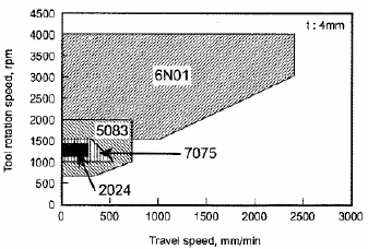
Fig. 2: process windows for several aluminium alloys. Solidus temperature: 502ºC for AA2024, 477ºC for AA7075, 574ºC for AA5083 and 582ºC for AA6061 [16].
This phenomenon of pin slippage may also explain the absence of molten pool during the FSW process. When the liquid state is reached, the process adjusts itself in order to return in a solid state welding. The local material melting in front of the tool may be confirmed by the presence of liquation in the thermo-mechanically affected zone (TMAZ) [17, 18]. Moreover, this phenomenon may explain the discrepancy between the numerical models of temperature (800ºC) and experiments (550ºC) observed by Colegrove and Shercliff [19]. However, the local melting is highly argued in the literature and no consensus is still adopted.
2.2. Material Flow
The complex flow around the FSW tool can be decomposed into three simpler flow components [20] (i) The first one may be considered as a cylinder of the welded material in rigid body rotation separated from the rest of the weld by a cylindrical shearing surface, i.e. a surface of velocity discontinuity (see Fig. 3.a). This rotating cylinder is conceived as attached to the FSW tool and its rotational speed is equal to that of the tool spindle. Its boundaries expand toward the tool shoulder to take into account the shoulder shape. Moreover, its thickness slightly increases on the retreating side to accommodate the metal transfer to the rear of the pin as the pin moves. In the case of thinner materials, this cylinder may be defined as a conical region to take into account the shorter pin length. The shearing surface is therefore located between the shoulder corner and the pin bottom (see Fig. 4 [13]). (ii) The second flow component is a homogeneous and isotropic flow field equal and opposite to the welding speed (see Fig. 3.b). This uniform translation is usually called “extrusion movement” by analogy to the same manufacturing process. (iii) The third component is a ring vortex flow encircling the tool and bringing metal up on the outside, in at the shoulder, down on the inside and out again on the lower regions of the pin (see Fig. 3.c). This flow is driven by the threads and/or flutes on the pin and can be reversed if the direction of the threads or the tool rotation is reversed. This vertical motion is clearly underlined by tracer experiments [21, 22]. In Schmidt et al.’s experiments [21], with 4 threads along the pin length, a marker is exposed to about 18 cycles around the pin. This generally leads to the disruptions and dispersion of the marker. As shown in Fig. 3.d, the combination of these three flows results in the formation of straight-through and vortex currents depending on the location. The material close to the advancing side travels in the rotating cylinder for a longer arc and is exposed to the axial flow of the ring vortex for a longer time. Consequently, the vortex current brings the metal to the bottom of the weld. Hence, vortex current residues are released to the advancing side in order to conserve the material. On the other hand, the straightthrough current occupies the retreating side as the metal in this region is exposed to the ring vortex for a short time. The relative amount of straight-through and vortex currents apparently fluctuates, perhaps due to an alteration in shear vs. friction slip on the shoulder surface [20]. These phenomena have been highlighted by Heurtier et al. [23, 24].
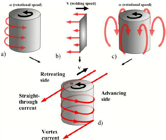
Fig. 3: Three incompressible flow fields: a) rigid body rotation, b) uniform translation, c) ring vortex, d) combination of the three flow fields.
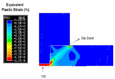
Fig. 4: Equivalent plastic strain during FSW process. Courtesy of Dong et al. [13]
Colegrove and Shercliff highlighted this complex metal flow by numerical simulation [19]. Fig. 4 shows in-plane velocity vectors of this simulation on horizontal planes at positions z = 0.1 mm (Fig. 5.a), 3.2 mm (Fig. 5.b, at mid-thickness) and 6 mm (Fig. 5.c, under the shoulder) from the bottom face. In all positions, a stagnation point is observed in the advancing side. The material close to this point is entrapped in the vortex current and flows around the pin. In the retreating side, straight-through currents are clearly underlined throughout the thickness. At mid-thickness (see Fig. 5.b), a large rotating region is observed around the tool, the solid line delineating the strain-rate equal to 2.s-1. This limits the cylinder in rigid body rotation illustrated in Fig. 3.a and approximates the boundary between the weld nugget and the TMAZ. Finally, Fig. 5.a shows the rotating material under the pin and it can be noted that the rotating tool above strongly influences the material flow in this region. This vortex flow, associated to the high temperature due to the extensive friction and metal work under the pin (see Fig. 1.c and Fig. 4), explains the complete welding of sheet root in the case of butt configuration. Indeed, the pin length is generally smaller than the sheet thickness to avoid the wear or the breakdown of the pin on the backing.
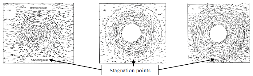
Fig. 5: in-plane velocity on horizontal planes at positions z = 0.1 mm (a), 3.2 mm (b) and 6 mm (c). Numerical simulation of AA5083 FSW. Courtesy of Colegrove et al. [19]
Dong et al. suggest a “boundary layer”’ phenomenon in the stirring region [13]. This phenomenon may be quantified by the feed ratio (k) between the welding speed (v) and rotational speed (ω) (see Eq. 2).

Equation 2: (k) feed ratio (mm/tr), (v) welding speed (mm/s), (ω) rotational speed (tr/s).
The feed ratio measures the size of this boundary layer, which can be related to material flow properties under given temperature and pressure conditions, i.e. given FSW conditions. As shown in Fig. 6, a range of feed ratio (k) can be determined either experimentally [25] or numerically to obtain an acceptable weld quality under given welding conditions (material type, material thickness, tool shape).
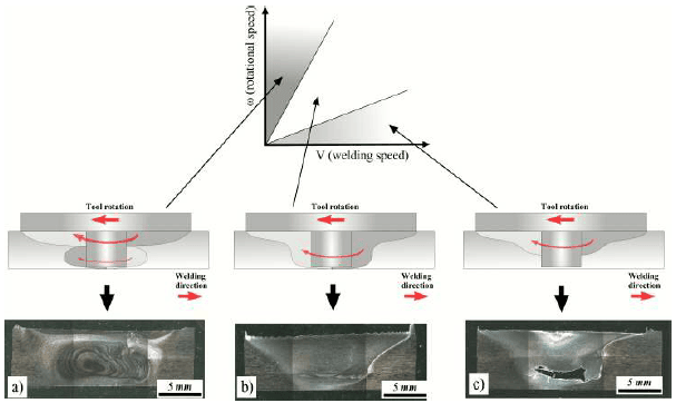
Fig. 6: Weld quality as function of feed ratio. FSW of AA6061, thickness of 8 mm [25].
For high (k) ratios (see Fig. 6.c), the minimum boundary layer for stable material flow may not be established leading to a lack of material feeding in the weld bottom, i.e. in the colder region. For low feed ratios (see Fig. 6.a), an overstirred situation may occur. In this case, the rotational speed is high compared with the welding speed, causing a high heat generation and stirring under the shoulder. Consequently, the material in this zone may rotate more than in the weld bottom. This unstable condition causes the appearance of two nuggets and, in extreme conditions, the wormhole type defect. Between these limits, the flow boundary layer is stable, leading to a sound and free defect weld as shown in Fig. 6.b.
Accéder à l’article scientifique complet
Vous venez de lire un extrait de ce document scientifique sur le soudage par friction-malaxage. Pour accéder à l’intégralité du document au format PDF, veuillez remplir le formulaire ci-dessous.
Section snippets
3 – Tool Parameters
As seen in the previous chapter, the quality of FSWed joints are significantly affected by the welding parameters [26, 27]. The rotational speed of the shoulder-pin assembly, the welding speed, the downward forging force and finally the tool design must be optimized to obtain a sound and homogeneous weld [28]. This chapter attempts to summarize the different designs and tool parameters that can alter the characteristics of a FSW joint: shoulder diameter, pin size and shape (see Fig. 7 …
3.1. Shoulder diameter and shape
3.2. Pin size and shape
3.3. Threaded and flute type pin
4 – Case studies
A number of tools have been developed during the last 15 years and used to join different materials, component thickness and joint types [42]. For the welding of thin sheets (< 12 mm), the most used tools are the cylindrical threaded pin and the Trivex™ due to their relative simple shape to machine on the short pin. For thicker materials (> 12 mm), the Triflute™ and Whorl™ are generally chosen. For lap joint, the most used tools are the Flared-Triflute™, Skew™ and the whisk types …
4.1. Butt joint configuration
4.2. Lap joint configuration
Conclusions
For the last fifteen years, progresses in FSW technology have been mainly related to new tool development and a better understanding of the process. The design of the FSW tool shoulder-pin system influences significantly joint quality and reduces the loads during the process. The present review was based on an extensive literature survey on the influence of tool geometry the selection of the FSW process parameters, the interactions between the tool and the metallic sample, and the resulting …
Acknowlegments
The authors thank P. Dong from Battelle, Murr. L from University of Texas, D. Hattingh from Nelson Mandela Metropolitan University, Colegrove P. and H. Shercliff from Cranfield University, Russell M. from TWI and Buffa G. from Viale delle Scienze for the agreement to use their results.